Hall-Θ
Release status: working
| Description | Hall effect endstop sensor
|
| License | GPL v2
|
| Author | |
| Contributors | |
| Based-on | [[]]
|
| Categories | |
| CAD Models | see files
|
| External Link |
Contents
Description
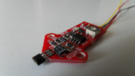
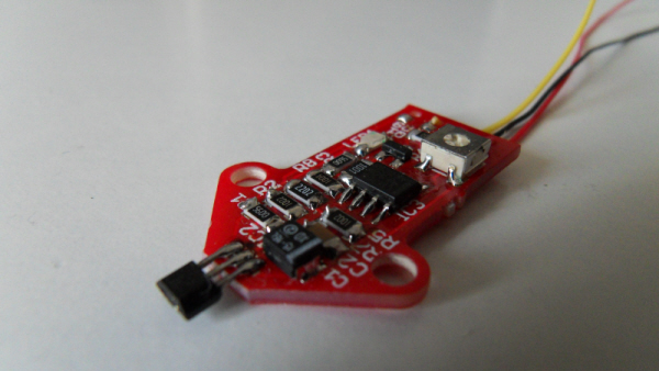
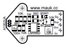
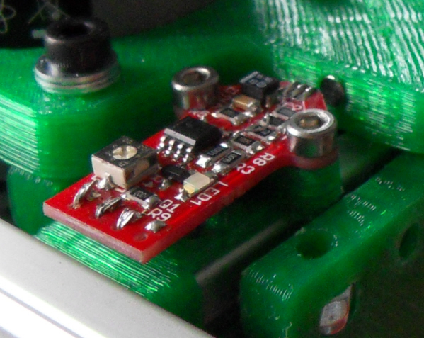
The Hall-Θ is a 32mm long Hall Effect Sensor PCB that reacts to magnetic forces.
It is powered by 5V DC, and has dual output (analog and digital).
When the magnetic field gets stronger, the output of the sensor will go to either Vcc or GND (south or north pole) in a linear way.
With a magnet of 4mm in diameter and 2mm thick(4x2), the reaction starts at approx. 6mm and reaches Vcc at approx 1mm distance to the sensor.
Analog output
The analog output comes straight from the sensor and is (when no magnetic force is applied) 2,5V.
When the south pole of a magnet approaches the sensor, the voltage will go up to Vcc.
When the north pole of a magnet approaches the sensor, the voltage will go down to GND.
If the Hall-Θ is used as an endstop device, 1 unit can be used for min and max endstop.
This can be done by applying a north pole to one side, and a south pole to the other.
Digital output
Digital output only works with south pole magnetics.
When the output voltage becomes greater than the Vref, the Digital output will go from 5V to GND.
Vref is regulated by a potentiometer.
Board images
Files
The holders for mendel and Cartesio are found at Thingiverse[2]
Parts List
This page is under development
Assembly Instructions
First of all make sure your soldering iron has a tip of 0.8mm or less, and make sure its clean.
That part is so important, when soldering SMD, that I will repeat it: make sure the tip is clean.
Clean means, there is no rest tin on it, but also means that when you hold tin to it, the tin immediately flows. So without pressing the tin to the tip.
If it does not flow, cool the iron, and clean it with a knife. Do not cut but rather scrape the tip and then heat it back up while holding tin to it.
Now you have a proper working soldering iron.
When soldering SMD always start with the smallest components and work your way up.
Put tin on 1 pad on the board, place the component with tweezers and hold, solder that 1 pad and then the other(s).
The last component will be the hall sensor itself. Put the pins in the holes and bend the pins 90 degrees. Now the sensor is aligned with the board.
Cut the pins so they do not stick out on the other side(1mm)
Note that the sensor should stick out about 2 mm from the board, to ensure you can bend the sensor in a 90 degree angle opposed to the board.
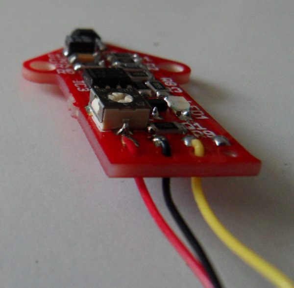
Now attach the cables to the board.
First cut off 1 mm of insulation and put tin on the wire
Then push the wire through the hole at the pad, from the bottom to the top, and solder it to the pad.
Pushing it through the hole makes sure the cable does not break from the pad when the cable moves/vibrates.
Setup
Solder the connector that comes with your "motherboard" to the cable coming from the Hall-Θ.
Download the Hall-Θ holder of choice at Thingiverse [3]
Mount the holder to the Hall-Θ and to the machines frame with M3(or M4 for Cartesio) bolts.
You probably want the sensor at a 90 degree angle from the board, since this is where you are going to measure.
Mount it at about 3mm distance from the place where you actually want the Axis to stop.
The sensor should be at 3mm distance from a plastic printed part.
Now to get to the interesting part: mounting the supplied magnet.
Make a mark on the plastic printed part nearest to the sensor.
Drill a hole of 3mm 2mm deep.
Make the hole a bit soft by holding a (hot) soldering iron to it, and push the magnet into the hole.
Do NOT hold the hot soldering iron to the magnet, or you will be left with a round metal piece.(which is a dead magnet)
For digital application make sure the south-pole is facing outward, otherwise the whole thing will do nothing and you have to take the magnet out again, which is a pain, I can tell you.
You can test which side is south-pole by holding the magnet to the Hall-Θ sensor, 1 side of the magnet will engage the LED, and 1 side will not.
Connect the connector to the "motherboard".
Make sure in the firmware the endstop is set to invert, because it switches from 5V to GND.
It is not required to have pullup resistors enabled in your firmware, because they are on the board it self.
If it is already enabled, leave it, it will not interfere.
For digital application you can now fine tune where the axis should stop by turning the potentiometer on Hall-Θ.
