Gen7 ExtensionBoard USB B 1.0
Release status: working

| Description | Part of Generation 7 Electronics
|
| License | GPL v2
|
| Author | |
| Contributors | |
| Based-on | [[]]
|
| Categories | |
| CAD Models | |
| External Link | (none)
|
This is an extension board for Generation 7 Electronics providing an USB connection. It's based on an Microchip MCP2200. Data transfer speed is specified by the chip manufacturer to be up to 921600 baud, or eight times the usual 115200 baud.
Contents
How to get it
PCBs
Get PCBs from Traumflug.
Like all Gen7 designs, this one is designed to be manufactured on a RepRap, too. You can make PCBs yourself, of course. How to do this on a RepRap or a general milling machine is described on the Gen7 main page. You'll find links to release documents, Gerbers, PDFs and such in the Github repository.
Parts
Get Parts Kits from Traumflug.
If you want to assemble the collection yourself, open the layout file with gEDA's PCB and export a "BOM".
Assembly Instructions
- To find out which components to put where, have the layout open on your PC screen.
- PCBs fabricated with Voronoi paths need more heat, so raise your soldering iron's temperature by about 20 deg Celsius.
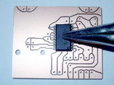
- Start with the MCP2200, as this is a bit more fiddly than the other components. It is a small outline integrated circuit package (SOIC) and has very small surface mount leads commonly used in automated reflow soldering. Still pin spacing is wider than usual, so manual soldering can be accomplished with patience and care. Searching the internet for "hand soldering SOIC" or similar keywords will yield several written and video tutorials on the subject in case the following doesn't work for you.
- To solder a pin, heat the track close to it with the soldering iron, then add a bit of solder between the iron and the pin. The solder should flow under/around the pin nicely.
- To check your work, hold the board against a light source. Shadows show you any solder bridges.
- If there are solder splashes in the isolation tracks, put flux onto this spot and heat again for a moment.
- The header pins are the standard type. See the pictures on how to make them fit.
Assembly in Pictures
Click on the pictures to view them bigger.
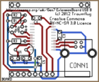
This is the board layout, viewed from the component side.
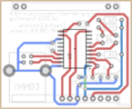
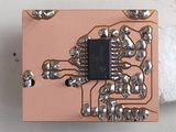
This is the board layout, viewed from the copper side. Note, the MCP2200 chip is on this side.
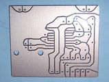
This is the real board. Compare to the previous picture to find the MCP2200's place.
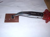
Look how bent pliers can make a convenient weight for holding the chip while the first pins are soldered.
Check the pin 1 orientation now. Got the place? Then you should have something like this.
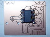
Now you can solder pin by pin, just like through-hole pins. Heat the copper close to the pin, then dip in a bit of solder wire and the solder will flow smoothly between copper and pin. As you can see, a bit of excess solder doesn't matter, the isolation tracks will remain free.
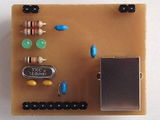
Now solder everything else, from the flattest to the highest parts. The pins for the connection to the main board ...
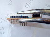
... are inserted like this: The left four pins are as they usually come from your supplier, push the right four pins through with pliers before soldering (these plug into the main board later so better to keep the gold plating at the end free of solder).
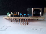
This picture shows four pins as bought (on the left), four pushed down with two already soldered (on the right).
Everything soldered? Great! The extra unconnected pins on the other edge of the board are to stabilise it when plugged in.
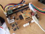
This is the board after inserting it into the main board.


Assembly Checks
As the chip has no socket and has to be soldered early in assembly, no voltage checks can be done before inserting it.
- Double-check the chip pins are soldered onto the right copper pads. It's fairly easy to misalign it by a pin spacing.
- Plug the board into the Extension Board header.
- Put your power supply into standby mode.
- The single wire bridge should measure 5 V against ground.
- In your host operating system, a new serial device should appear. On Linux, that's /dev/ttyACM0, where the 0 can be a higher number, if similar devices are plugged into the PC as well.
Setup
There's nothing to do for basic usage. The adapter should work out of the box. You can go to the next chapter on this page.
Programming the MCP2200
If you want to hack it anyways, that's possible. There's a MCP2200 Configuration Utility which allows to do advanced configuration, like changing the blinking of the Rx/Tx indicators (see also these two forum postings). This tool also allows changing the general purpose I/O (GPIO) pins of the chip. An available library can be used to write custom windows applications using this. Not very helpful in the Linux world, the tool doesn't run using Wine.
An attempt to hack the chip using open source tools is usbio. If you want to dive in even further, the MCP2200 is a custom-programmed PIC18F14k50 and can be reprogrammed. :-)
Commissioning
After plugging in the board and turning on standby power, a new serial device should appear in the host's operating system. Connect to it using a serial terminal and see wether you can communicate with the firmware. The baud rate required depends on the firmware in use and is set the same way as with a traditional serial port; serial terminals usually do the right thing. On the command line, "stty" should work well.
Each dis- and re-connect should reset the ATmega, visible by the firmware's startup message.
Troubleshooting USB
- Traffic indicator LEDs (RxLED, TxLED) don't work: that's default setting for factory fresh MCP 2200s. See #Programming the MCP2200.
No known serious pitfalls, so far.