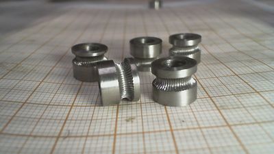
DIY Hobbed Drive Gear
Release status: working
| Description | A mounting jig to make stainless steel hobbed drive gears.
|
| License | |
| Author | |
| Contributors | |
| Based-on | |
| Categories | |
| CAD Models | |
| External Link |
Introduction
I was wondering if it was possible to make a stainless steel hobbed gear drive using a M3 turning tap. Some techniques described in RepRap are based on pressing taps mounted in drilling machines against bolts, using bearings mounted in a vise to let the bolt spin. This method works reasonably well for soft iron bolts, but when I tried to replicate the method in hard stainless steel rods, the only result I got were lots of broken taps.
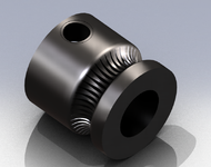
In this page I describe a simple mounting jig that was used successfully to make MK8 stainless steel hobbed drive gears. Besides the jig, the technique requires a lathe and a milling machine to make precision machined gears.
Overview
The standard MK8 Drive Gear have an hob diameter of 7 mm. This is the diameter of MK8 Drive Gears listed in Drive-gear and manufactured by Aus3D, RepRap.me, TaoTac.com and Twelvepro.com. Others manufactures offer a diameter of 7.25 mm (Garage Days 3D and Alfa-Tech3D) or 7.1 mm (TriDPrinting.com).
Perhaps the last option has an actual hobbed diameter slightly greater than 7 mm to consider the bite of the teeth, but 7.25 mm is a diameter too large to be explained by the bite. To make things worse, the manufactures does not specify if this diameter is the major or minor diameter of the gear thread.
There is some uncertainty about the optimal number of cuts on the gear's circumference and due to the reason explained before, I preferred to calculate the diameter gear from scratch. For this, lets consider that a M3 tap has an major diameter of almost 3 mm and a pitch equal to 0.5 mm. The number of cuts on the gear internal circumference must be a multiple N of 0.5 mm. If the internal diameter of the gear’s thread is d, we have:
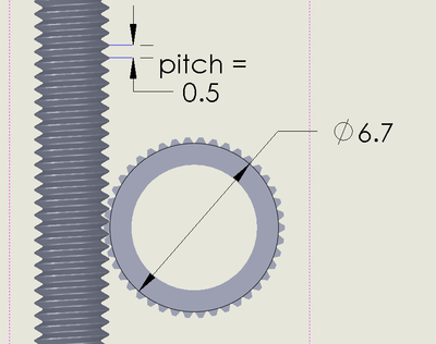
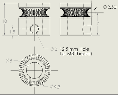
So, for a diameter d = 6.7 mm, we obtain an N equal to 42 cuts as shown in figure 1. Considering a thread high equal to 0.25 mm, the outer diameter of the gear’s thread will be 6.7 + 2*0.25 = 7.2 mm. As the hole required to tap an M3 thread is 2.5 mm, the total diameter of the gear will be 7.2 + 2.5 = 9.7 mm. Figure 2 gives the gear dimensions that will be made in next sections.
- Making Grooved Gears
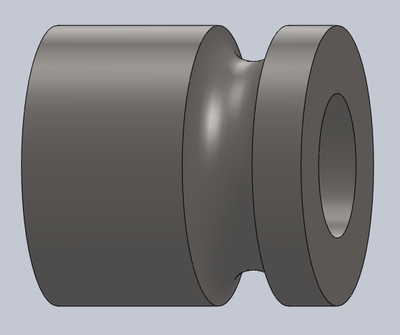
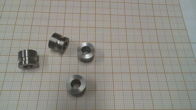
With the necessary gear dimensions established, a lathe is used to turn a stainless steel rod to make several bored grooved gears as shown in figure 3. The lathe operations required are straightforward and can be seen in detail in the video at the end of the page. Figure 4 shows some grooved gears to be hobbed in next steps.
- The Jig
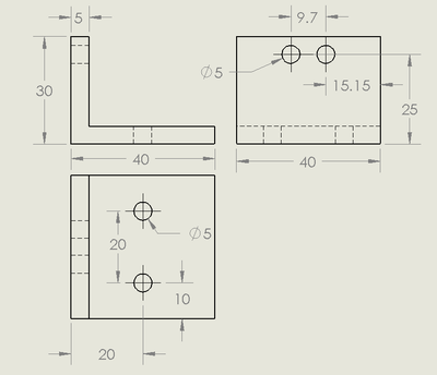
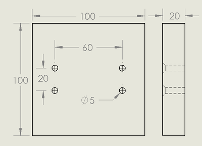
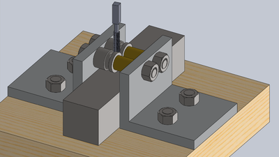
Figures 5 and 6 show a technical drawing of the main parts of the jig used to hobbing the gears grooves. They can be produced in a mill with L shaped aluminium profile and plywood. The most important measure is the distance of 9.7 mm for the two M5 screws that will support the gears. This distance needs to be precisely set in order to make sure that the two gears are perfectly tangent, without gaps. Among these parts, it is required four flat-head M5 x 25mm screws, two hex-head M5 x 35 mm screws, six M5 nuts and two brass washers to keep the gears constrained between the L shaped aluminium supports.
- Material for hobbing
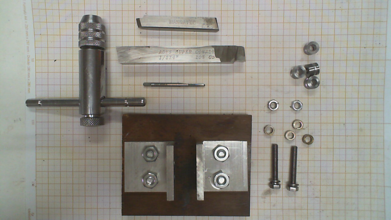
Figure 7 shows the required material for hobbing. Among the jig itself, with its screws and nuts, we need an M3 Tap and two hard steel bits.
- Using the Jig
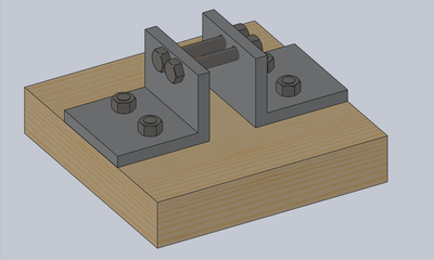
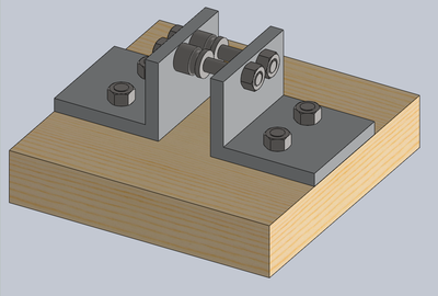
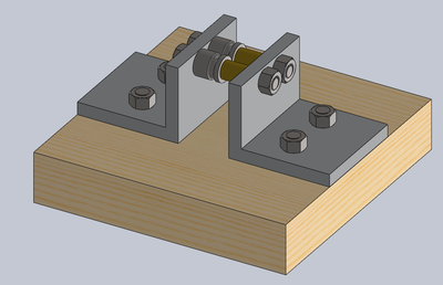
All the steps described in this and next sections are shown in the video at the end of the page. Figure 8 shows the jig with all the screws and nuts mounted. Figure 9 shows the same fixture but with the gears inserted, Figure 10 adds the brass washers to keep the gears constrained between the two L shaped aluminium supports. It is better to turn those washers in a lathe after measuring the distance needed to block the gear movement along the screw axis.
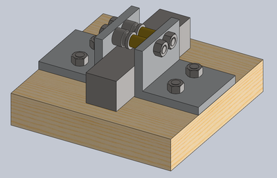
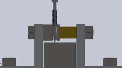
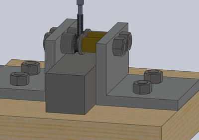
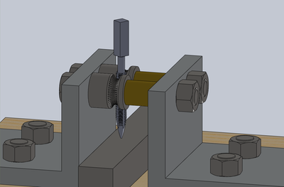
Next pass is to insert a hard steel bit bellow the gears groves (Figure 11). This is mandatory, otherwise the M3 tap would reach and penetrate the wooden base of the jig. A hard steel bit blocks the vertical movement of the tap, and as the thread proceeds, the two gears will rotate in opposite directions.
It is somewhat tricky to insert the tap in the channel formed by the two gears grooves. Several turns with some pressure may be needed before the M3 tap touches the hard steel bit. But after that, the gears starts to roll in opposite directions and the tap will turn easily. After the gears have completed one turn (Figure 14), we replace the bit with a smaller one (figure 15) so that the tap shaft advances in the already semi-hobbed groove (a tap shaft is thicker in the upper half). An easier way to hob the gears is to use a column drilling machine: Attach the tap to the spindle, hold the jig with a vice and advance the tap shaft in to the grooves of the gears. Do this with the lowest rotation speed. After repeating this procedure with several pairs of gears we get precisely machined hobbed gears, shown in figure 16.
To finish, we move to a milling machine to make the grub screw holes. This final step is straightforward and is shown in the video below (14:15).
