Columbus
Release status: unknown

| Description | Documentation of Columbus R&D
|
| License | |
| Author | |
| Contributors | |
| Based-on | |
| Categories | |
| CAD Models | |
| External Link |
Columbus is a 3D printing device that is being developed to answer the inspiring challenges of the Kartik M. Gada Personal Manufacturing Prize. The current stage of development is: preliminary design. In this stage brainstorming sessions are combined with due diligence to narrow down goals and define objectives. Various materials are extruded by Columbus via a Cartesian arrangement which consists of a belt driven gantry for positioning in the X/Y axis and a print bed that is raised and lowered by a linkage for positioning along the Z axis.
Contents
Overview
//Under construction, more coming soon!
"This web-page, therefore, is about making a useful virus that is as big as a fridge." -Adrian Bowyer, Wealth Without Money, 24 Feb 2006
//More on that concept to come.
The main requirements of the Gada Prize are:
- Print at least three different materials, including one that is usefully electrically conductive.
- Demonstrate the ability to print electronic circuit boards.
- Any print beds must be of a material which may be reused with minimal refurbishment for at least 20 print cycles.
- Maintain a total materials and parts cost under $200.
- 90% of the volume of the device's components shall be printed.
- Demonstrate a build volume greater than 300 mm (11.81in) x 300 mm (11.81in) x 100 mm (3.94in).
- The capacity to print a full set of components for a complete replica of itself within 10 days unattended save for clearing no more than one printer head jam.
- The ability to print autonomously without a PC attached.
- Uses no more than 60 watts of electrical power.
Columbus Specifications
The table below outlines the specifications of the machine.
| Metric[Imperial] | |
|---|---|
| Manufacturer | Anyone |
| Model | Columbus |
| Technology | FFF (Fused Filament Fabrication)/Thermoplastic extrusion |
| Price of all materials | TBD |
| Annual Service Cost | TBD |
| Size | 400 mm (15.75in) x 400 mm (15.75in) x TBD mm (TBDin) |
| Weight | TBD kg (TBDlbs) |
| Build Envelope | 300 mm (11.81in) x 300 mm (11.81in) x TBD mm (TBDin) |
| Materials | TBD |
| Material Cost | TBD |
| Speed | TBD |
| Accuracy | TBD |
| Finish | TBD |
| Volume of printed parts to replicate | TBD |
Design Philosophy
//Under construction, more coming soon!
"Truth and beauty...are almost like the ideal conjoined twins that a scientist would want to date." -David Bolinsky, David Bolinsky Animates a Cell, Mar 2007
//More on that concept to come:)
- Required reading:
- Wealth Without Money, Adrian Bowyer
- The Self-replicating Rapid Prototyper ─ Manufacturing for the Masses, Adrian Bowyer
- The Emergence of Open Design and Open Manufacturing, Michel Bauwens
- Required viewing:
- David Bolinsky Animates a Cell, David Bolinsky
- Ross Lovegrove Shares Organic Designs, Ross Lovegrove
Design Tree
- Preliminary Design
- Prototype One
- Redesign One
- Prototype Two
- Redesign Two
Nomenclature
Due to the nature and scale of this project it is expected that hundreds – if not thousands – of files will be created to properly document and exploit the various conceptual designs, prototypes, and official releases. Because one can only name a file just so many things before language is exhausted, the following nomenclature will be used for naming all Columbus files:
- COL-XXX-XXX-XXX-X
- All files begin with the first three letters of the Team name, in this case COL.
- The second set of three digits represent the project the component is in.
- If a file is purely experimental then it may be noted as such by substituting the project name with "TEST". Example: COL-TEST-150-...
- The third set of three digits represent the assembly within the project.
- The fourth set of three digits represents the part number within the assembly.
- The last placeholder represents the release status: an uppercase letter for released revisions (A,B,C...) or a number for unreleased revisions (1,2,3...)
- For released revisions the letters I (as in iceberg) and O (as in orange) are skipped due to their similar appearance to 1 and 0 respectively.
- Example: COL-125-010-007-B. This is read as: Columbus, project 125, assembly 10, part 7, revision B.
Key Concepts
Progressive Construction
It is expected that those who assemble Columbus will be in one of two main categories: those that have an existing 3D printer (i.e. Darwin, Mendel, MakerBot, RapMan) and those that do not. While it will be difficult to achieve the $200 price range with an existing 3D printer, it will be nearly impossible to reach that goal without such a device. In an effort to increase the number of potential users Columbus is being designed with a "progressive construction" in mind (also called Ship of Theseus) construction. In this scheme the user will first assemble a RepStrap which contains many of the components of the full size Columbus (i.e. stepper motors, electronics, straight rods). This device will then print the remaining structural components. Finally, the initial device is dismantled and it's components are combined with the parts it printed to form the compete Columbus printer. It is hoped that this routine will not only save the first time user money, but will also familiarize the user with the components and construction ideas they need before assembling the complete unit.
Structure
Print Bed
Control Systems
Workbook
General Notes
In accordance with the official Gada Prize rules regarding documentation and transparency - as interpreted by the RepRap Core Team and others - all documentation for this project will take place here in this wiki. If there happen to be any "Other Spaces" out there that have documentation for this project, then such information is posted there only after it is posted here.
- The following notes help to keep this workbook in a neat and orderly condition and shall be generally adhered to throughout all levels of documentation.
- All dimension and temperature nomenclature shall include both SI and Imperial units. SI units shall be first followed by Imperial units in brackets. Examples: 100 mm (3.94in) and 40 °C (104 °F).
September 2010
1 SEP '10
- Design work is progressively advancing. The latest design, COL-TEST-104-0, adds more detail to the X/Y gantry that was proposed in the COL-TEST-103. A method has been devised that allows a single stepper motor to drive both axial belts. This method currently relies on a drive shaft coupled with a gear train to simultaneous transfer moments (torque) from the stepper motor. See the views below.
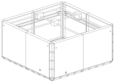
COL-TEST-104 Trimetric View.
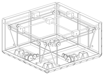
COL-TEST-104 Trimetric View, some components removed for clarity.
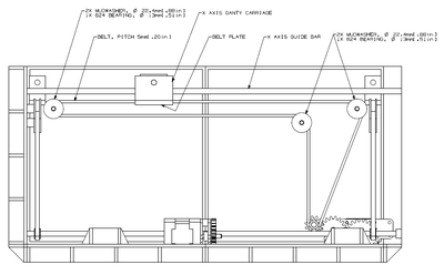
COL-TEST-104 Front View, some components removed for clarity.
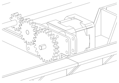
COL-TEST-104 Belt Drive detail, NEMA 17 stepper motor shown.
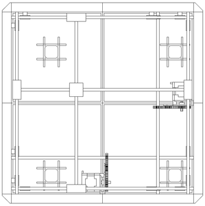
COL-TEST-104 Top View.


This method uses NEMA 17 stepper motors, specifically Lin Engineering's 4018M-04 which can be found relatively inexpensive at Alltronics. A simpler method is envisioned that replaces the gantry support rods with threaded rod. This slows down the gantry a little and could make it more accurate, but more importantly cheaper to build. Such a method will be evaluated in the COL-TEST-105 design. Note that the features that look like # signs in the above views are future attachment locations for heated print bed components.
- Other thoughts:
- While designing the gear train used in the COL-TEST-104 it became painfully obvious that gear design is no simple task. While there are many well meaning tutorials and formula explanations and so forth out on the web, they all seem to attack the problem from a general - typically academic - point of view. This tactic is of course very appropriate when appealing to a large audience, however it is also very distracting to the individual who simply wants to design a gear and move on. In an effort to ease my own and other's future gear design headaches I think I am going to start a Gear Design wiki page sometime soon.
- Please do! Pick your favorite CAD program, the wiki loves them all! :D --Sebastien Bailard 00:35, 10 September 2010 (UTC)
- Columbus must print a support material. There is no way around it, in order to make cheaper Repraps a support material is absolutely necessary. Preferably a water soluble material similar to what is used in Objet's Alaris 30.
- Thanks for your time and as always feel free to post something in the Columbus discussion page or in our official forum.
- --Isaac Olson 11:13, 1 September 2010 (UTC)
August 2010
8 AUG '10
Over the last two years I have followed the RepRap movement with particular interest. However, it took the Foresight Institute's act of throwing down the gauntlet with the Gada Prize before I finally got involved with this awesome community of builders. For the last two weeks I have been thinking a lot about how to make the structure of a 3D printer 100% "printable". I decided that my design needed to free up as much internal volume as possible. In order to do this I brought the load bearing members as far away from the center of the machine as possible, thus forming an exoskeleton-like enclosure. I have designed several panels that can be linked together with printable fasteners (more on those in the future). See the following images:
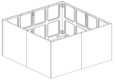
TEST-102: Preliminary panel arrangement.
TEST-102: Nearest panels removed for clarity.


Note that the panels are pocketed to reduce the amount of print material. This is only a preliminary design, I haven't done any stress analysis yet. Please leave a comment or ask a question in Columbus's discussion page. --Isaac Olson 04:07, 9 August 2010 (UTC)
18 AUG '10
In an effort toward keeping things organized, the new Nomenclature section has been created. Like most things, the systematic approach to naming files outlined there brings with it a host of pros and cons (but mostly pros.) The main pro being that it simply keeps things organized, if it is followed every time a file is made. Some of the cons are that it has a learning curve, it isn't intuitive, and Team members can still make files with duplicate names. To help alleviate some of these issues the Nomenclature section will eventually be moved to it's own subpage. A table will be added for logging what files have been created and reserved, so everyone on the Team knows what number to go to next if they want to create something. This subpage, and associated table, will serve as a central "repository" for all Columbus files. At first it will only be useful to the Team, for documenting designs and reasons already stated. However, it's hoped that eventually the RepRap community at large will use this subpage to document their improvements to Columbus. Here is an example of what I'm thinking:
| FILE ID# | TYPE | DESCRIPTION | AVAILABLE FORMATS | CREATED/RESERVED BY |
|---|---|---|---|---|
| COL-TEST-103-0 | SOLID MODEL ASSEMBLY | This assembly was created to test the idea of external pocketing of structural panels. | .pdf, .stl | --Isaac Olson 04:14, 19 August 2010 (UTC) |
| COL-TEST-103-101-0 | SOLID MODEL PART | This part is the first attempt at external pocketed panels. | ... | --Isaac Olson 04:14, 19 August 2010 (UTC) |
| COL-TEST-103-102-0 | SOLID MODEL PART | This part... | ... | --Isaac Olson 04:14, 19 August 2010 (UTC) |
| COL-TEST-104-0 | SOLID MODEL ASSEMBLY | This assembly will test the idea of a hexagon layout for internally pocketed panels. | N/A | --Isaac Olson 04:14, 19 August 2010 (UTC) |
- In this case yellow highlighted cells indicate a number that is reserved. If this solution proves to be too bulky then the files may be migrated to SourceForge or similar, since that is most likely where the code will end up anyway.
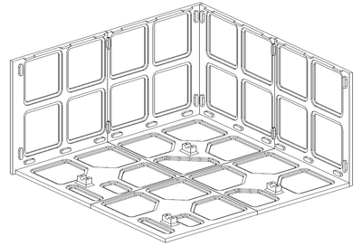
- Panel and general structure design have been steadily advancing. For the last week a "externally pocketed" panel arrangement has been evaluated (see Trimetric View below.) It is referred to as the -103. External here refers to the exterior of the enclosure formed by the panels, and not the exterior a panel itself. "Internally pocketed" follows a similar line of thought. While externally pocketed panels are ascetically pleasing, it is expected that future Columbus designs will use internally pocketed panels. This reduces the amount of parts to print/buy because internal attach points and hardware can be "grown" right out of the panel surface. For this same reason the complexity of the remaining parts to print/buy is greatly reduced. The -103 uses this to some extent, in the trimetric view note the knobs where the gantry support rods pierce the panels. These holes, and associated flanges, serve as a guide to level the rods in construction and as an attach point. The components of the -103 are meant to glued together, as opposed to the -102 (the previous workbook entry's design) being held together with printable fasteners. Again, there are numerous advantages to both schools of thought, in the end Columbus will most likely be held together with a mixture of the two. The -103's cartesian gantry design was inspired by the clip RepRap XY lighter darwin by tigertalar. See video below:
<videoflash>lBzRjTB9JBw&NR=1|475</videoflash>
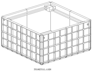
TEST-103 trimetric view.
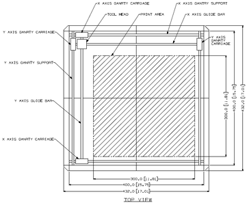
TEST-103 top view.


So far the only departure from tigertalar's design has been to allow only a single guide rod per axis to pass through the toolhead. However, some sort of mechanism may have to be devised to drive both axial belts at the same time. This gantry configuration can be quite compact in theory, see Top View. If this general layout works then there should be an abundant supply of area on two sides of the print bed for extra tools! Thanks for your time and as always feel free to post something in the Columbus discussion page or in our official forum. --Isaac Olson 04:14, 19 August 2010 (UTC)
Further reading
- The Box-Shaped T-Slot Bot Deutsch, the RedBot, the Columbus, and the tigertalar "RepRap XY lighter darwin" all have "the same" abstract partially parallel Cartesian drive train configuration, which lets every motor spin in a fixed location -- rather than moving one or two motors up and down (or left and right) like most other arrangements.