Arduino Mega Pololu Shield
Release status: Working

| Description | A RepRap etch resist printable circuit board that fits on the Arduino MEGA and holds interchangeable stepper driver carriers and the rest of RepRap's electronics.
Arduino MEGA based modular RepRap electronics.
|
| License | |
| Author | |
| Contributors | |
| Based-on | |
| Categories | |
| CAD Models | |
| External Link |
Contents
Summary
RepRap Arduino Mega Pololu Shield, or RAMPS for short. It is designed to fit the entire electronics needed for a RepRap in one small package for low cost. It is a single layer designed board that is printable on your RepRap with the etch resist pen method, or home fabbed with toner transfer. At the same time it is based on the powerful Arduino MEGA platform and has plenty room for expansion. The modular design includes plug in stepper drivers and extruder control electronics on an Arduino MEGA shield for easy service, part replacement, upgrade-ability and expansion. Additionally as long as the main RAMPS board is kept to the top of the stack a number of Arduino expansion boards can be added to the system.
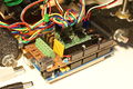
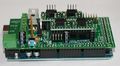
Mendel printed RAMPS wired to Mendel.
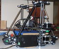
Mendel with RAMPS in enclosure mounted.
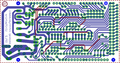
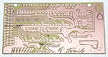
screen capture of 2-sided RAMPS layout
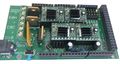
commercially fabbed 2-sided RAMPS wired to Mendel


Features
- It has provisions for the cartesian robot and extruder.
- Expandable to control other accessories.
- 3 mosfets for heater / fan outputs and 2 thermistor circuits.
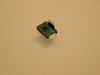
- Fits 4 Pololu A4983 stepper drivers
- Pololu boards are on pin header sockets so they can be replaced easily or removed for use in future designs.
- The pin headers for the stepper motor outputs are placed on top of the Pololu boards saving routing them on the main shield.
- I2C and SPI pins left available for future expansion.
- All the Mosfets are hooked into PWM pins for versatility.
- Servo style connectors are used to connect to the endstops, motors, and leds. These connectors are gold plated, rated for 3A, very compact, and globally available.
<videoflash type="youtube">0k_KArg_sgA</videoflash>
Assembly Instructions

Component Soldering
Use your preferred circuit board manufacturing method. :) If you are doing point to point wiring make sure to read that section first
- Top wires. (This step is not required if using a two sided PCB) Make sure they are clear of other components to be soldered later
- Resistors as shown to the right.

- Small 100nF capacitor, C4
- LED - short pin towards the wider opening in the symbol, down in this case.
- Cut the 2 row pin headers into 2x3 (6)blocks, 7 of them needed. Solder these for microstep selection jumpers, and endstop jacks. It is easiest to place all these and hold them in place with a card to flip board for soldering.
- Cut the 1x10 pin header to 4 pins long and solder it in the T1 T0 holes for thermistor jack. Solder one of the end pins first, straighten the pins to be perpendicular to the board and solder the rest of the pins.
- 1x16 socket headers into place for the stepper driver sockets.
- Power connector
- Screw terminal block
- Reset switch
- Pass-through headers that will connect the shield to the Arduino board. Can be later for short pin headers
- Solder the large capacitors as shown lower right.
- They must be inserted in the correct orientation. + to the top or left.
- Mosfets
- They must be oriented in correctly
- The big yellow MF-R500 fuse
- The diode can be omitted, it may be needed in the future for printing from SD or USB. This will power the Arduino from the shields 12V input. Diodes must be oriented correctly. If you are using higher than 12V to power the shield you should omit the diode to prevent damage to the Arduino and stepper drivers.Warning: The high side of the stepper boards are designed to accept up to 35V, but if you do this the heater and other high side outputs will be at that voltage also. You may need to adjust the heater resistance, etc.
- Thoroughly check for shorts (This is crucially crucial for DIY etched boards.)
- Check for continuity between each and every pin to the pins next to them and GND, 12V, 5V (VCC).
- Set your meter to beep for continuity, hold a probe on GND and check all soldered pins. If it beeps check if it is supposed to be GND and contine. Repeat for 12V and 5V.
- Solder the pin headers on to the stepper driver boards.
- For this design the power and control pins go down towards your new shield and the motor pins(1a,2b,2a,2b) on top of the board (component side) so the motors can be plugged directly in.
- See image on right.
- Make the cables up for the endstops.
- WARNING In order to keep the PCB at a printable resolution two wires have been flipped from the traditional opto endstop boards. The signal pin has been moved to the outside of the connector.
- Hooking these up incorrectly can damage the components.
- Endstop End: Vcc-Sig-Gnd ; Shield End Vcc-Gnd-Sig
- Connect at least the minimum endstops.
- Put the connectors on the motor wires.
- Shown is the type used for servos in RC projects. See Stepper Motors for info on motors.
- Use a 4 pin 0.1" connector to terminate the thermistor wires.
- Use the two receptacles on one end, leaving the other two open for extra thermistors.
- Connect the cable so the 2 wires go to T0
- Connect the 2 heater wires to E0H and the + connection above it.
- If changing to an unverified firmware it is best to verify heater circuit function with a meter before connecting heater to prevent damage to the extruder.


Connecting Power

The power connector plug may not be obviously labeled, looking at the power connection the positive is on the left and the negative is on the right of the plug.
If you think you may have mistakes you can install only one stepper driver during initial testing.
Point to point wiring when using a proto shield


It is possible to make this circuit with a proto shield by running wires directly between the pins. Make sure to check the prototype shield you use for pin holes that have traces tying them together. You most likely will have to cut some traces to keep from shorting circuits together. The board used here is the Arduino Mega shield one manufactured by Arduino. I only had to cut traces in about 4 places and it only took a couple seconds each with the little grinding bit on a dremel tool. Pictured below are the traces that need cut on the Tinker-It shield, both traces need cut in the small red circle, the top trace cut twice in the big circle to isolate the pins there.
If wiring a shield make sure to leave the area above the usb jack and ISCP header clear of components or the board is spaced / electrically insulated sufficiently to avoid shorts to the Arduino Mega board components.
Firmware and New Pin Assignments
You will need the Arduino software at http://www.arduino.cc/en/Main/Software to upload the firmware to Arduino Mega.
Here are the pin definitions for this board.
RAMPS v1.1c
The following values need to be entered to "Arduino Mega pin assignment" in the "pins.h" file of the firmware if not already configured.
// RAMPS v1.1c
#define DEBUG_PIN        13

#define X_STEP_PIN (byte)26
#define X_DIR_PIN (byte)28
#define X_MIN_PIN (byte)3
#define X_MAX_PIN (byte)2
#define X_ENABLE_PIN (byte)24

#define Y_STEP_PIN (byte)38
#define Y_DIR_PIN (byte)40
#define Y_MIN_PIN (byte)16
#define Y_MAX_PIN (byte)17
#define Y_ENABLE_PIN (byte)36

#define Z_STEP_PIN (byte)44
#define Z_DIR_PIN (byte)46
#define Z_MIN_PIN (byte)18
#define Z_MAX_PIN (byte)19
#define Z_ENABLE_PIN (byte)42

// Heated bed

#define BED_HEATER_PIN (byte)8
#define BED_TEMPERATURE_PIN (byte) 1


//extruder pins

#define EXTRUDER_0_STEP_PIN (byte)32
#define EXTRUDER_0_DIR_PIN (byte)34
#define EXTRUDER_0_ENABLE_PIN (byte)30
#define EXTRUDER_0_HEATER_PIN (byte)10
#define EXTRUDER_0_TEMPERATURE_PIN (byte)2

#define EXTRUDER_1_STEP_PIN (byte)23
#define EXTRUDER_1_DIR_PIN (byte)25
#define EXTRUDER_1_ENABLE_PIN (byte)27
#define EXTRUDER_1_HEATER_PIN (byte)9
#define EXTRUDER_1_TEMPERATURE_PIN (byte)8
RAMPS v1.0
Original PCB that was available from Ultimachine in Sept 2010.
This board can be used with FiveD without modifications with the above pin definitions. The extruder heater ouptuts will be on the screw terminals marked D10. You can cut the traces on top of the board and wire pins 8 and 9 to the other 2 mosfets if needed for heated bed, etc. Pins 11 and 12 can not currently be used with the FiveD firmware due to a conflict with the interupt timer . The following pin definitions can be used with Tonokip_Firmware(Note baud rate defaults to 115200 in this firmware) controlled by RepSnapper Manual:Introduction software.
// RAMPS v1.0
#define X_STEP_PIN         26
#define X_DIR_PIN          28
#define X_ENABLE_PIN       24
#define X_MIN_PIN           3
#define X_MAX_PIN           2

#define Y_STEP_PIN         38
#define Y_DIR_PIN          40
#define Y_ENABLE_PIN       36
#define Y_MIN_PIN          16
#define Y_MAX_PIN          17

#define Z_STEP_PIN         44
#define Z_DIR_PIN          46
#define Z_ENABLE_PIN       42
#define Z_MIN_PIN          18
#define Z_MAX_PIN          19

#define E_STEP_PIN         32
#define E_DIR_PIN          34
#define E_ENABLE_PIN       30

#define LED_PIN            13
#define FAN_PIN            -1
#define PS_ON_PIN          -1
#define KILL_PIN           -1

#define HEATER_0_PIN        12
#define TEMP_0_PIN          2   // MUST USE ANALOG INPUT NUMBERING NOT DIGITAL OUTPUT NUMBERING!!!!!!!!!
Schematic

Warnings
The endstop pins are Signal - VCC - GND, instead of the VCC - Sig - GND like the rest of RepRaps boards. Make sure to wire them correctly. This is done to allow squeezing fatter traces on the printable board.
Ingredients
Source
| FILE ID# | TYPE | DESCRIPTION | DOWNLOAD |
|---|---|---|---|
| File:ArduinoMegaPololuShield.zip | Eagle Files | These are the files you need to make the boards | media:ArduinoMegaPololuShield.zip |
| File:RepRapjr.lbr | Eagle Libraries | The components used in this board are here. see Eagle_Library | media:RepRapjr.lbr |
This board is mostly based on Adrian's Pololu_Electronics and work by Tonok. copper etch resists methods suggested by Vik circuit design based mostly on Adrian's Pololu_Electronics Used Joaz's pin definitions for initial layout
Bill of Materials
| ID | Description | Quantity | Part Number |
|---|---|---|---|
| U1 | Arduino Mega | 1 | |
| U2,U3,U4,U5 | Pololu A4983 carrier | 4 | |
| C4 | 100nF capacitor | 1 | |
| C5,C8 | 10uF capacitor | 2 | |
| C6 | 100uF capacitor | 1 | |
| R1,R7 | 4.7K resistor | 2 | |
| R2,R3,R4,R5,R6,R8,R9 | 100K resistor | 7 | |
| Q1,Q2,Q3 | N-channel Mosfet | 3 | STP55NF06L |
| D1 | Diode | 1 | 1N4004 |
| F1 | PTC resettable fuse | 1 | MF-R500 |
| J2 | 5.08 Eurostyle screw terminal | 1 | 282837-6 |
| LED1 | 5mm Green LED | 1 | |
| S1 | Push button switch | 1 | FSMRACD |
| X1 | Power jack | 1 | MSTBA1 (5.04mm spacing 2 connector) |
| 2 x 12 pin header | 2 | ||
| 2 x 9 pin header | 1 | ||
| 10 pin header | 1 | ||
| 2 x 18 Pin Stackable Female Header | 1 | ||
| 8 Pin Stackable Female Header | 5 | ||
| 6 Pin Stackable Female Header | 1 | ||
| 16 Pin Female Header | 4 | ||
| Circuit Board | 1 | v1.1 |
Wish list
This shield would like to replicate with the following external boards
- Additional Stepper Driver
- DC Driver
- Thermistor
- Thermocouple
- SD Card
- Control Panel w/LCD
- Ethernet
- Host USB
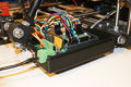
Electronics Enclosure
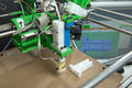
OK, this is an enclosure for the RAMPS. It has a mount built in for a 40mm fan and LED.
Shown printed in PLA. There is talk that it is currently unprintable in ABS due to warping.
It uses 2.8mm holes to for the 3x16mm cap screws that mount it and the Arduino stack inside. These holes print a little undersized with my configurations and hold a 3mm screw pretty good.
| IMAGE | FILE ID# | TYPE | DESCRIPTION | DOWNLOAD |
|---|---|---|---|---|

|
File:RAMPS1-1case.zip | STL | All the stl files for the v1.1 enclosure in a zip | media:RAMPS1-1case.zip |

|
File:RAMPS ADfiles.zip | Alibre Design Files | These are the original design files. | media:RAMPS ADfiles.zip |

|
RAMPS-Case-Top3 | STL | The lid for the enclosure. Has mount for 40mm fan. Chose the one that fits your vs of the board with or without UltiMachine logo. | media:RAMPS-Case-Top3v1-1.stl
media:RAMPS-Case-Top3v1-1noUlogo.stl media:RAMPS-Case-Top3v1-0.stl |

|
RAMPS-Case-Base3 | STL | The bottom half of the enclosure. Chose the one matching your vs. | media:RAMPS-Case-Base3v1-1.stl |

|
File:RampsWindow.stl | STL | Covers teardrop holes and serves as reset button lever | media:RampsWindow.stl |

|
File:RampsResetButton.stl | STL | Attached through window with 3mm filament. | media:RampsResetButton.stl |

|
File:RampsMountSpacer.stl | STL | Spacer to raise enclosure up above the bottom nut outside the frame vertex. | media:RampsMountSpacer.stl |
Showcase
printed on a RepRap Mendel with the etch resist method Using_cad.py
attempt at printing labels with sharpie
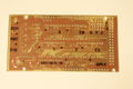
Two-sided PCB Built v1.0
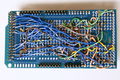
messy back of the first prototype of RAMPS -- built on a generic megaproto shield with point to point wiring, rather than a custom RAMPS PCB
RAMPS with standard pin headers
Add your pics here!!!


Change Log
- v1.1 September 30, 2010
- Replaced power barrel jack with plug-able screw terminal
- Added jumpers to select micro-stepping on stepper driver boards
- Added debug LED
- Changed mosfet pins to be compatible with FiveD firmware
- Reduced number of 100uF capacitors to 1
- Added 100nF capacitor to 12V input
- Put auxiliary 12VIN and GNDIN pads in a straight line
- Silk Screen and bottom layer cleaned up
- v1.0 Original RAMPS PCB design
- v0.1? Point to point wired Arduino MEGA Prototype shield
Trouble Shooting
- Check List
- RAMPS shield firmly seated on Arduino MEGA
- No stray wires/metal to cause short
- All connections firmly seated, screws tight
- Power connection oriented correctly
- Thermistor connected to T0
- Firmware uploaded
- Stepper driver potentiometers to a sane setting
- Heater wires properly connected
Heated Bed
Warning: Do not attempt this if you are afraid your mosfet will release magic smoke. This has not been tested on V1.0, and might not work as well due to thinker mosfet traces It is possible to run your heated bed off of the RAMPS shield without a relay. Some users may be inclined to use a mosfet as it will release magic smoke and cut power, rather than a relay's inclination to fail in the closed state. How to: You need to jump the two pads where the resettable (yellow) fuse normally goes. The through holes are small, but the pads are big, so it is better to use a larger gauge wire and solder on the pads. It is not as mechanically strong, but will let you use a bigger wire. On the Version 1.1 shield, it might be best to use D8, as it has thicker traces.