Aluhotend
Release status: in production
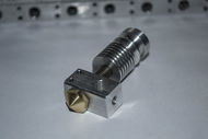
| Description | Aluminium and Stainless steel hotend for general purpose printing with ABS Nylon and PLA , designed as a drop in replacement for the jhead
|
| License | nc
|
| Author | |
| Contributors | |
| Based-on | |
| Categories | |
| CAD Models | |
| External Link |
Contents
Introduction
This is the Aluhotend in it's most current format currently it is a 4 piece design:
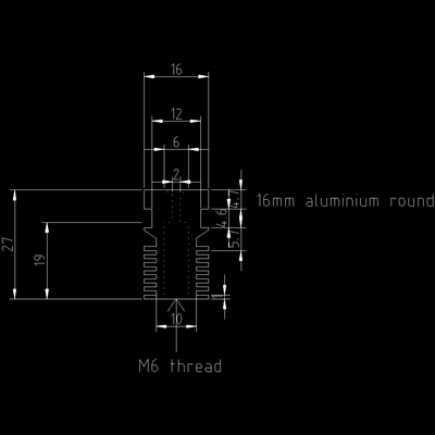
Heatsink - all of these are manufactured with a 2.5mm hole in the entry is drilled out before shipping to cater for 3mm use, the mounting point is dimensionally identical to the [jhead] and should mount in anything the jhead does.
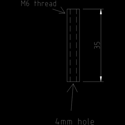
Thermal Barrier - these have taken a few forms before this one most of them have been turned and reduced in diameter from the outside leaving no room for a ptfe liner, the latest version the thermal barrier is a 35mm length of stainless steel threaded rod with a hole bored through it at 4mm , then either a 2mmID 4mmOD or a 3.15mmID4mmOD ptfetube is inserted.
the advantage with this configuration is that not only is the liner held captive by the heatsink the large diameter on the thermal barrier provides a great deal of strength and protect against crashes into the bed which would cause damage to previous versions.
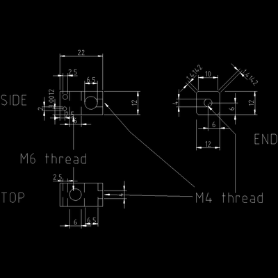
Heater Block - the design is based more on machining capability in the early stages than anything, it has 4 holes 2 of them are threaded the M4 threaded hole takes an M4 grub screw for retaining a heater cartridge or a resistor in the 6.5mm hole, the 6.5mm hole done at 6.5mm due the problems with heater cartridge diameters, which while they are sold as 6mm in diameter that isn't actually the case, some of them are oval in shape and will get jammed in a 6mm hole, making replacement impossible with damaging the heater block the holes for the thermistor are 2mm and 2.5mm which allows the use of a through hole type of thermistor the reasons behind this were mainly safety, the thermistor cannot physically fall out leaving the hotend to overheat.
Nozzle - the nozzle is a fairly standard M6 threaded nozzle, you can use just about any of the commonly available nozzles for the up! or makerbot and various other hotends which use an M6 threaded nozzle.
Assembly
1 - screw thermal barrier into heatsink (todo: insert pictures here)
2 - screw nozzle into heater block all the way (todo: insert pictures here)
3 - insert ptfe liner into thermal barrier cut off with about 6mm remaining on the end (todo: insert pictures here)
4 - screw thermal barrier into heaterblock until it hits the nozzle (todo: insert pictures here)
5 - back off nozzle by 1/2 turn (todo: insert pictures here)
6 - tighten thermal barrier by 1/4turn (todo: insert pictures here)
7 - tighten nozzle against thermal barrier (todo: insert pictures here)
Wiring it up
Dissassembly
is simply the reverse of assembly however if the hotend has been used it is advised to do it while it is hot otherwise the nozzle can be damaged
Usage
can be used normally just like most other hotends, one suggestion for easy feeding especially with 3mm filament is to cut the filament at an angle so that the pointy end wants the curl into the middle of the tubing, this will allow the filament to slide all the way down instead of a 90 degree curly end digging into the PTFE liner, this is somthing that should be done on any PTFE lined hotend to maintain the integrity of the PTFE liner and make it last as long as possible
swapping plastic and colors can be done simply by backing out the filament being used and loading the next up to 50mm of plastic should be pushed through the hotend preferably by hand to purge the old plastic out.
The temperature limit is about 245 C if fitted with an internal PTFE sleeve.
Standards of Filament
there are no particular standards for filament and each manufacturer seems to be different, in the early all metal hotends v1 and v2 some colors exhibited more back pressure than others which is why the ptfe liner was introduced at the time some colors like the florescent yellow would only run for a short time before jamming where as black and other colrs would run for months continuously with no issues, generally you want to run the best filament you can afford to run, for development purposes these hotends are tested in a production environment on filament which is in the lower part of the quality spectrum.
Cooling requirements
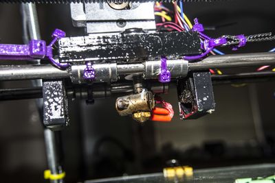
Cooling on this hotend is and has always been rather simple all of the setups i have built and tested this hotend with have been in the opposing fan configuration this setup allows both the cooling of the hotend and also the part , it also has the added benefit of redundancy if one fan fails during a print you still have one running see below as an example however it will function just fine on one.
Suppliers
| Supplier Name | Location | link | feedback |
|---|---|---|---|
| 3D industries Australia | Australia | link | - |
Drawings
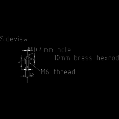
nozzle:
Internal hole depths:
2mm hole depth: this value determines the length of the orifice, ideally the orifice length should be about 0.5mm calculate this based on your drill type,
the 3.5mm hole is 7mm deep any less and it no longer becomes a compatible replacement for the up! nozzles,
- this value is likely to change in the future and we may have to make up different nozzles, for different hotends eg highspeed and retractionless,
Thermal Barrier:
Heater Block:
Heatsink:
Mounting
This Hot End is mounted to the extruder Cold End using a standard Groove_Mount.
