A5 Powder bed printer
Release status: Just started
| Description | Building a Powder bed 3D printer.
|
| License | GPL
|
| Author | |
| Contributors | |
| Based-on | |
| Categories | |
| CAD Models | |
| External Link |
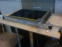
The purpose for the A5 Powderbed printer is for experimenters and hobbyist to try different powders, binders and fusion methods without fear of invalidating warranty on a commercial machine, it is also for artists to experiment with the materials and geometries available to digital creation.
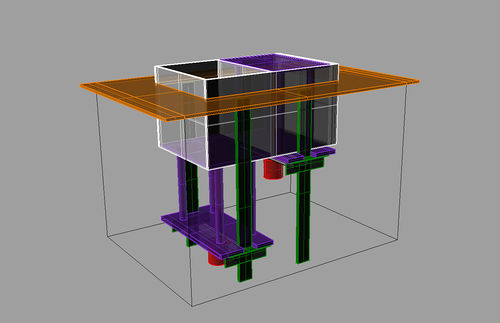
With this in mind, the machine has been designed to be modular, that is to say, the powder bins are the heart of the machine, applying a thin layer of powder being a common task with a smoothing roller or blade.
Powderbed printers have some advantages and disadvantages. The main advantage of a powderbed printer is that the powder provides the support for the part whilst being built and they can be fast in comparison, colours are a possibility with appropriate software. The disadvantages of a powderbed printer are the mess they make, good housekeeping is essential, without fusion the parts are not regarded as engineering grade, however the parts can be used for moulding, infiltrated or other secondary operations.
The surface of the powder or, TOP of the machine, can be regarded as a separate entity, the place where binder is applied or fusion occurs, and different equipment can be installed, a plotter driven by EMC2 or Mach3, flatbed printer, plotter or galvanometer guided laser etc to name a few.
A hopper system to dispense powder has a space saving advantage, but may not be as flexible with various powders, needing the powder to be engineered to suit the hopper or the hopper to suit the powder, with this in mind the trusted method of feed bin and part bin have been adopted, although this is no guarantee that the powder will spread in a thin layer out of the bag without some additives or sieving, but should give the most flexibility to use different powders.
The A5 Powderbed printer has been designed to be built with minimum cost by someone with average workshop ability and tools, where the use of machines that may not be available to others in building the prototype, alternatives are suggested.
A number of people have built powderbed printers, but a lack of detail makes it hard for many to build their own, I hope to build one and explain each step, so that others can follow, using equipment and materials that are off the shelf wherever possible.
if you want a finished solution, it may be better to wait until it is tried and tested.
Materials The Open 3DP project has been developing DIY powder printers for a few years. They've concluded that USG Hydroperm powder and rice wine "binder" gives good results and are very inexpensive to source.
A collection of recipes for powder printers
Powder related wiki pages can be found here
Printer HP DJ1000 HP DJ2050.. other printer candidates
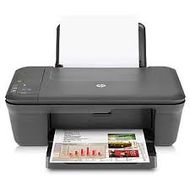
The HP DJ1000 was the printer of choice for initial development, it looks simple and cheap, and cartridges are refillable, at the time they were difficult to find due to being on special offer, so a HP DJ2050 was purchased instead, this looks like a DJ1000 with a scanner on top, hopefully the scanner will not present extra problems?.
Draw slides
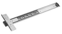
These are used for the powder bins, recoater and printer rail, (3 pairs), they are low friction, with little if any play and are cost effective. Concealed door slides,(500mm) at £11.50 for two are a cost effective option
Powder bins and mechanisms
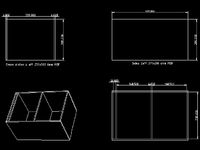
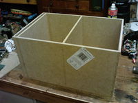
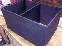
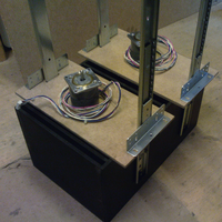
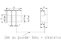
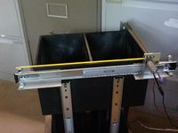
The powder bins are made from 6mm MDF, (£10) to the drawing below, "other sheet materials could be used, melamine coated mdf, tufnol etc", the store cut the parts on a wall saw, this ensures the cuts are square, (no charge for cutting). the apertures are A5 + 10mm all round, to aid part removal, the slot is for overflow The centre lines of the cross plates were marked out, and small holes for panel pins drilled, glue the edges and assemble, making sure all sides are as square as possible to avoid tight spots when the pistons are fitted, then tap in the panel pins, (use small pins to avoid splitting the MDF), double check that the whole thing is square, ( clamp if needed) and leave to set for 24 hours, I coated mine with wood stove paint, to seal it against moisture, which may cause swelling and distortion.
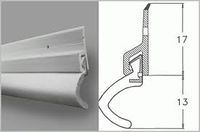
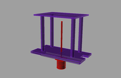
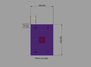
Pistons, The pistons need to move in a smooth manner,without jitter, slop etc, this is to ensure that each layer is directly above the previous layer, we also need to seal between piston and bins to prevent powder getting by, using door seal strip, cut the top piston plate to suit your bins, so that they will pass through without any tight spots but without excessive clearance.
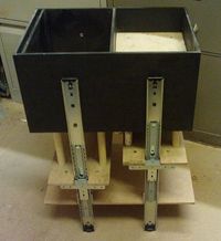
Draw slides are again used for the piston slides, to obtain maximum accuracy at minimum cost and effort.
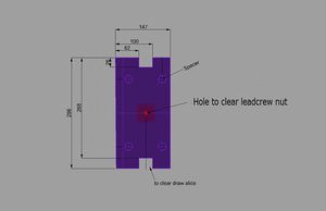
The top and bottom plate are made from 6mm MDF, they are not critical accuracy, the top plate will have the draught excluder to exclude powder, and the bottom plate is not a close fit to anything, the spacers can be wood broom handle cut to 197mm long, try to get them all the same length for each bin,
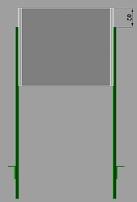
Mark on each side plate, the centre line for both bins, select which is to be the top face of the bins and mark 50mm down, and with a small clamp, clamp a slide to the bin so that the small hole is central to the line and the end of the slid is 50mm from the top, with a hand drill or pistol drill, drill out the hole in the slide and through the bin with a 5mm drill, countersink the inside face of the bin until the screw is flush, cut the screw so that it does not protrude through the nut, otherwise it will foul the runner, do the same for the other hole, making sure the slide is square to the bin, and mount the other slides this way.
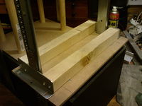
Brace bars, made from whatever you have available, I used 35mm square wood,cut them so they are a snug fit, not to tight or to loose, with the ends square, this brace bar adds rigidity.
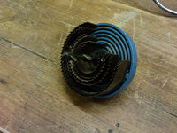
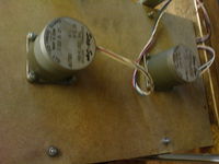
The piston spacers are 20mm wood dowel, cut to 197mm long, the motor plate is made from some of the remaining 6mm MDF, supported by alluminium angle, and the holes for the motors cut with a hole saw, the motors were salvaged and are probably old, the shafts are 1/4 inch and the mounting boss is 2inch dia, you will need to cut the holes to suit your motors.(see Motors)
Two motor couplings, made from brass, I did them on the lathe, but need to find a near net part that can be adapted for the job.
Another outstandingly poor video showing the pistons moving under motor power, (background noise is a Radio4 play) <videoflash type="vimeo">20962156|640|480</videoflash>
Motors The motors do not need to be high powered, the draw runners are low friction and provided the pistons and seals are not to tight and things are aligned well nema 17 motors should be up to the job, but it does depend on the build, if in doubt go for bigger motors Nema 23( too much torque is better than too little), if the motor misses steps the part will be spoilt.
Recoater
Draw slides again used for the recoater
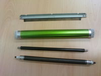
The job of the recoater is to spread a thin even layer of powder, although this can be done with a blade, a roller is usually a better option, a couple of laser toner cartridges were dismantled in the search for a suitable roller.
Laser toner cartridges seem to have a common format, having a static sensitive "drum", a magnetic roller and rubber roller, with a couple of scrapers, although the dimensions can vary from cartridge to cartridge.
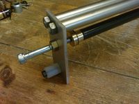
The Drum roller is thin walled alluminium with plastic inserts, making it fragile to work with, the magnetic roller is also a tube, but the rubber roller is 6mm rod with a 12mm rubber coating having centres in each end, although a diameter bigger than 12mm would be preferable, it was decided that this was a good candidate for our recoater.
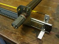
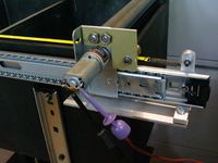
A small DC geared motor was selected to power the roller and move the recoater using the wire drive principal, although a stepper motor could be used limit switches will be used for reversing etc.
the adapter was made on the lathe ( need near net shape) the output speed of the motor is 130 rpm at 12v, this can be adjusted with a potentiometer to suit the powder if needed.
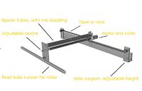
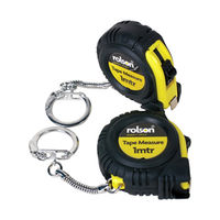
The recoater uses one motor to move the recoater and spin the roller, although a backup design is available using two motors if the roller speed is to slow, the motion is a type of wire drive, but using tape from a small tape measure.
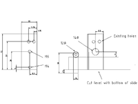
I have had the recoater working from a power supply, the speed looks ideal between 9v and 12v, My motor has a 14mm diameter register, the hole for this on the draw slide intersects existing holes, this makes it tricky to drill, I used a milling machine with a slot drill, if you are not using a miller then it may be better to mark out and chain drill inside the circle, then file to the line, or else clamp very firmly in a drill press and use a hole saw.
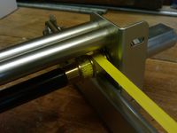
The roller pulley has two flats to accommodate small pins that hold the tape, panel pins could be used, the flats need to be deep enough to allow the panel pin head to lie below the surface and not cause a bump, the recoater is not difficult to make but requires patience with the fiddly bits, it must recoat every layer so needs to be reliable, its worth taking the effort to make sure everything is aligned and working well.
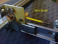
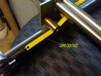
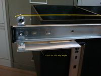
I have made a small modification, see images, after dismantling an old HP printer to study the parts, ( they look very similar to the 2050 internals) I realized that the tape drive as it stands would not allow enough space, so a plate was added with a roller to lower the tape to provide clearance, I have not yet dismantled the HP2050 as more work needs to be done on the software first.
The recoater is mounted using aluminium angle, 1 1/2x 1 1/2 x 1/8, this was stock available, one piece would be just as good but I only had a limited amount available The initial idea was to have a top plate with everything mounted on it, but it would have needed to be rigid and therefore fairly heavy, so outriggers in the form of aluminium angle have been adopted, and a lightweight cover will be made to catch the powder overflow along the sides of the bins to protect the runners and make housekeeping easier, (maybe slopping sides)
A print-rail has been extracted from an old HP printer, it appears to be very similar to the print-rail on the 2050, " maybe the metalwork is similar in some models"
an adapter has been made and the whole rail clamped to a runner, which has been placed on the bins to ascertain position and dimensions, (details to follow)
Interface
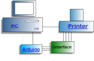
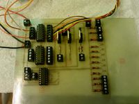
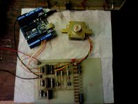
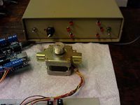
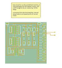
The interface or electronics, house the arduino and circuit board to move the stepper motors, DC motor, solenoids etc, to allow manual setting up of the powderbed printer ( filling with powder, getting ready to print) and automatic run, The circuit has been done in Fritzing, ( the layout can be improved)and is relatively low cost, 3.5 pitch terminal blocks have been used to make life easy, but are not essential, wide gaps between tracks allow for the use of resist pen by hand, although the prototype was done with laser and Iron method.
You are not restricted to using the above electronics, stepper motor drive boards are an option, they should be capable of driving bigger motors with more current, but the arduino code will need to be modified to step and direction signals instead of signals for each coil, also cooling may need to be considered as drive boards may produce more heat.
One method to get more current flow from an IC is to stack them, the darlintons can be stacked if they are getting to warm,
Parts made with machinery that need alternative solution
Leadscrew nut................do drawing
motor to leadsrew adapter.....see drawing
Recoater Roller pulley................. see drawing
Files
| FILE ID# | TYPE | DESCRIPTION | AVAILABLE FORMATS | CREATED/RESERVED BY |
|---|---|---|---|---|
| Description | Description of powderbed printer | .pdf, .odt | johnrpm | |
| Powderbins | Making the powder bins.(unfinished) | .pdf, .odt | johnrpm | |
| Interface | fz | fritzing circuit and etchable pdf | .fz.zip, .pdf | johnrpm |
| Recoater | building the recoater. | .xml.zip, .stl.zip | --Example User 12:00, Today's Date 20xx (UTC)|- | |
| Electronics | Arduino Mega pin allocation. | johnrpm |
