A4982-Dual Stepper Board
Release status: Experimental

| Description | A4982 Dual Stepper Board with STM8 MCU for VREF / MS1 / MS2
|
| License | GPLv3+
|
| Author | |
| Contributors | |
| Based-on | |
| Categories | |
| CAD Models | Eagle
|
| External Link |
Contents
Dual A4982 Expansion Board
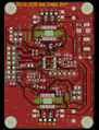
- A4982-DSB-reverse.jpg
A 48x68mm expansion board providing two 2.0A A4982 stepper drivers, designed for general-purpose use on a wide range of 3D Printing Electronics, powered from 9-29 volts DC, compatible with 3.3v and 5v boards, and providing an on-board NTC temperature resistor, dual STEP/DIR/EN for motor control and an STM8 MCU for software-driven configuration of VREF, MS1 and MS2. Also the STM8 (which is optional) may be programmed to run completely independently, potentially running its own G-Code firmware and being controlled through standard reprap G-Code motion control software (pronterface, Cura etc).
Prototype
Features:
- Two independent A4982 steppers
- Experimental 2-layer (1oz copper) design
- Relatively large PCB to support proper thermal dissipation (48x68mm)
- 1 on-board 100k NTC with a 4.7k bias
- compatible with 3.3V or 5V electronics
- Supports Motor DC Power input from 9 up to 29 volts.
- 14-pin 2.54mm DIL Header with 1 ADC (thermistor), I2C (communication with the STM8) and SPI (unused)
- On-board (optional) STM8 MCU which may be programmed to independently set MS1, MS2 and VREF for each A4982 stepper
- Optional jumpers and Potentiometer for cost-saving scenarios or manual configuration.
- STM8 may be programmed to run cut-down versions of Marlin (or other) firmware and may directly control each A4982 stepper.
Design considerations
TODO
STM8 Header
- Pin 6: GND
- Pin 5: UART TX
- Pin 4: UART RX
- Pin 3: SWIM / XMS1
- Pin 2: RST# (low to reset)
- Pin 1: VCC
AUX2 Header
AUX2 is a 14-pin (2x7) header at the left of the board. Pin 1 is marked (bottom right, row 9). This header has two sets of STEP / DIR / ENABLE# lines (one per stepper), I2C (for communication with the STM8) and an ADC sensor. and is connected to a 100k NTC thermistor in the middle of the PCB. It may be used to check the temperature, to detect if the PCB is overheating. The SPI pins of this header are unused and should not be connected.
- Pin 14 (row 1, left): SCL (for communication with the STM8)
- Pin 13 (row 1, right): SDA (for communication with the STM8)
- Pin 12 (row 2, left): MOT2EN# - pull low to enable
- Pin 11 (row 2, right): STEP2
- Pin 10 (row 3, left): NC
- Pin 9 (row 3, right): DIR2
- Pin 8 (row 4, left): NC
- Pin 7 (row 4, right): MOT1EN# - pull low to enable
- Pin 6 (row 5, left): NC
- Pin 5 (row 5, right): STEP1
- Pin 4 (row 6, left): 100k NTC Thermistor, 4.7k biased.
- Pin 3 (row 6, right): DIR1
- Pin 2 (row 7, left): VCC
- Pin 1 (row 7, right): GND
Source, BOM, Schematics
- GPLv3+ licensed CAD Files, git repository and relevant component datasheets: http://hands.com/~lkcl/a4982/
- Schematic: http://hands.com/~lkcl/tmc2660/a4982dsb.pdf
- BOM: http://hands.com/~lkcl/tmc2660/a4982dsb.html