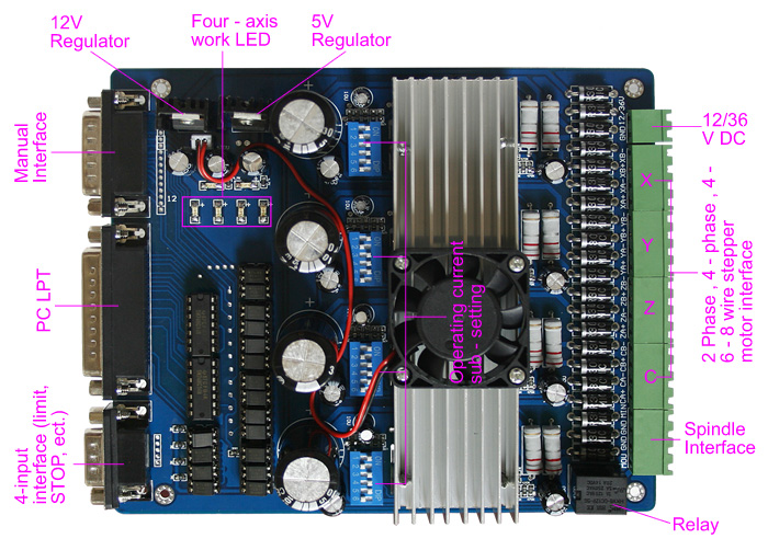
4 Axis TB6560 CNC Stepper Motor Driver Board Controller
| Input Power | 12 - 36V DC Note that many forums state that this board dies in smoke if powered over 24V |
| Stepper motor drive current | 1.5A - 3A/phase |
| Drive type | Double-pole constant flow PWM actuation output |
| Compatible Stepper motors | 2 or 4 phase, 4,6 or 8 lead stepper motors, 3A max. |
| Dimensions | 18 * 11 * 4 cm (L*W*H) |
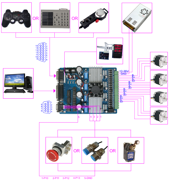
The pinount in the provided document was wrong (completely) so I traced the pcb for real values and here they are:
| Pin | LPT | Driver |
| 1 | (strobe) | X-CW/CCW |
| 2 | (D0) | RELAY (heater) |
| 3 | (D1) | Z-CLK (step) |
| 4 | (D2) | X-ENABLE |
| 5 | (D3) | Z-ENABLE |
| 6 | (D4) | Z-CW/CCW (direction) |
| 7 | (D5) | Y-CW/CCW (direction) |
| 8 | (D6) | E-CW/CCW (direction) |
| 9 | (D7) | E-CLK (step) |
| 10 | (ACK) | INPUT (limit switch) |
| 11 | (BUSY) | INPUT (limit switch) |
| 12 | (PE) | INUPT (limit switch) |
| 13 | (SEL) | INPUT (limit/stop switch) |
| 14 | (AFEED) | Y-CLK (step) |
| 15 | (ERROR) | N/C |
| 16 | (INIT) | X-CLK (step) |
| 17 | (SELIN) | Y-ENABLE |
| 18 | GND | GND |
| 19 | GND | GND |
| 20 | GND | GND |
| 21 | GND | GND |
| 22 | GND | GND |
| 23 | GND | GND |
| 24 | GND | GND |
| 25 | GND | GND |
You may find that the fourth stepper driver enable pin is not available on the DB25 connector. If so, it is on the DB15 at pin 1.
ALTERNATE: In some revisions at least, the enable pin for the fourth driver/channel is *SHARED* with the enable pin for the third channel ( assuming you wire them in the order XYZE, it means that your Z and E drivers share their enable line ).
| Pin | CNC |
| 1 | E-ENABLE |
Note: The enable pin's are pulled high so if you do not drive them
all drivers are enabled by default.
| Current Setting | 1 | 2 | Decay Mode Settings | 3 | 4 | MicroStep Settings | 5 | 6 |
| 100% | ON | ON | FAST | ON | ON | 1 | ON | ON |
| 75% | ON | OFF | 25% | ON | OFF | 1/2 | ON | OFF |
| 50% | OFF | ON | 50% | OFF | ON | 1/8 | OFF | ON |
| 25% | OFF | OFF | SLOW | OFF | OFF | 1/16 | OFF | OFF |
The currently recommended settings for the DIP switches are:
X & Y axis: 25% Current, Slow Decay Mode, No Microstepping ( ie use Microstepping value of 1 )
Z: To-be-determined. Currently we believe the required power setting may need to be higher than X& Ym, but we arent sure. No Microstepping.
Extruder: To-be-determined. No Microstepping.
NOTES: You need to avoid microstepping unless you have the absolute latest firmware, because with *lots* of microstepping interrupts on all axes, you will get packet loss on the USB-Serial Host communications. For now, the fix is to avoid microstepping. It makes it easier to debug lost steps, etc anyway.

