User:Cisox/WolfStrap
Release status: unknown

| Description | documenting a generic tool/artpiece
|
| License | |
| Author | |
| Contributors | |
| Based-on | |
| Categories | |
| CAD Models | |
| External Link |
Contents
- 1 Main Body
- 2 Extruder
- 3 Electronics
- 3.1 RAMPS
- 3.2 Introduction
- 3.3 Features
- 3.4 Safety Tip
- 3.5 Support
- 3.6 Build and Use
- 3.7 Ingredients
- 3.8 Showcase
- 3.9 Change Log
- 3.10 How to get it
- 3.11 Troubleshooting
- 3.12 Sanguinololu
- 3.13 Features
- 3.14 Derivatives
- 3.15 Bugs
- 3.16 Schematic & Board Images
- 3.17 Where to get it
- 3.18 EAGLE files, parts list
- 3.19 Assembly Instructions
- 3.20 Alternative build, using IRLB8743 Mosfet
- 3.21 EXTERNAL
- 3.22 Software
- 3.23 Final Check
- 3.24 Microstepping Jumper Settings
- 3.25 SD / Bluetooth Adapters
- 3.26 Revision History
- 3.27 Generation 6 Electronics
- 3.28 Generation 7 Electronics
- 3.29 Generation 3 Electronics
Main Body
Wooden Parts
| Quantity | Description | Type | Comments |
|---|---|---|---|
| 2 | 445x18x45mm | Board | Drawer slides X-axis |
| 2 | 200x18x45mm | Board | Drawer slides Z-axis |
| 1 | 300x18x45mm | Board | Attachment for the captive nut, Y-axis |
| 2 | 50x18x45mm | Board | Attachment for the captive nut, X-axis and Z-axis |
| 2 | 415x18x70mm | Board | Base Frame |
| 2 | 450x18x70mm | Board | Base Frame |
| 2 | 350x18x70mm | Board | Vertical frame, X-axis |
| 1 | 160x18x70mm | Board | Z-axis, extruder mount |
| 1 | 110x18x70mm | Board | Z-axis, motor mount |
| 1 | 300x400x18mm | Board | Bed. A 5 mm plywood may be used to reduce mass. |
Everything is plain softwood. The cheap kind from the hardware store. (It is not intended to be long lasting) Be carefull to choose only straight boards and planks. Leave the warped behind. If you intend for the machine to last longer, better quality wood can be used and glued together as well as using screws.
All dimensions are rough measurments, some adaptations will be required.
Non-Wooden Parts
| Quantity | Description | Type | Comments |
|---|---|---|---|
| 2 | 250mm | Rail | Come in pairs. Four total rails. |
| 1 | 450mm | Rail | Come in pairs. Two total rails. |
| - | 4x25mm SPAX screws | Fastener | A good handful of screws (Ex. Spax) |
| - | 3x15mm SPAX screws | Fastener | A good handful of screws |
| - | 4x35mm SPAX screws | Fastener | A good handful of screws |
| 3 | NEMA 17 bipolar stepper motors | Stepper | Be sure to get ones with at least 20mm of shaft length |
| 6 | 100x100mm brace | Fastener | Corner braces for base frame (Ex. Corner Brace) |
| 4 | 120x120mm brace | Fastener | Flat corner braces for base frame |
| Option 1: Threaded Rods | |||
| 2 | M10x350mm | Threaded rod | X-Y-axis |
| 1 | M5x200mm | Threaded rod | Z-axis |
| 4 | M10 nut | Fastener | X-Y-axis. 2 per axis. |
| 2 | M5 nut | Fastener | Z-axis. 2 per axis. |
| 3 | Aquarium tubing | Misc | Coupling purposes |
| 4 | Hose clamp | Misc | Coupling purposes |
| Option 2: Timing Belt | |||
| 1 | 840mm×5mm T5 pitch timing belt | Belt | Y-axis |
| 1 | 900mm×5mm T5 pitch timing belt | Belt | X-axis |
| 1 | M8x18cm | Threaded rod | Z-axis |
| 3 | M8 nut | Fastener | Z-axis |
| 1 | M8 brass plug | Fastener | |
| 1 | Cable tie | Fastener | |
| 4 | 60mm chair angle | Fastener | |
| Optional | |||
| 4 | 608 roller skate / inline skate / skateboard bearing | Bearing | |
The seat angle can be quite easy to convert with holders for 42mm flange NEMA17 steppers (see below) In Mendel timing belt kit is usually included in a Z-strap width 16mm. For one need only one Mendel 5mm wide, after splitting then remains a second.
Extruder
- The following extruder is Wade's Geared Extruder for 3mm filament. For 1.75mm filament use RepRap Universal Mini Extruder; or any other compatible extruder for either.
Printed Parts
| Quantity | Description | Type | Comments | Diagram |
|---|---|---|---|---|
| 1 | extruder block | RP | File:M8 Extruder 3.zip | |
| 1 | extruder idler block | RP | File:M8 Extruder 3.zip | |
| 1 | 11 tooth drive gear | RP | File:M8 Gears.zip | |
| 1 | 39 tooth M8 hub driven gear | RP | File:M8 Gears.zip | 
|
Non-Printed Parts
| Quantity | Description | Type | Comments |
|---|---|---|---|
| Feeder | |||
| 2 | 608 bearings, skateboard bearings | Bearings | |
| 1 | M8X50 bolt | Fastener | to be hobbed, M8x60 has a longer smooth part, allows a second lock-nut, and may be easier to find |
| 1 | M8 nut | Fastener | Nyloc works better, but a pair of nuts will also work |
| 4-5 | M8 washers | Fastener | to space the large gear clear of the motor retaining bolt heads |
| Idler | |||
| 1 | 608 bearing, skateboard bearing | Bearings | |
| 1 | (M)8X20 | Threaded rod | |
| 4 | M4X60 or M4X45 hex head bolts | Fastener | Hex head will work best (they won't turn), and longer than 45 mm will be easier to assemble if you can find them. |
| 4 | M4 nuts | Fastener | typically wing nuts |
| 8 | M4 washers | Fastener | |
| 4 | ~4mm ID springs | Spring | Sized to fit over an M4 bolt, unsprung length of 10-12mm, each spring providing 25-35N load. For a given filament drive force, you'll need about twice the spring force - i.e., if you want 100N of filament drive, your springs need to push with about 50N each. |
| 16 | M4 washers | Fastener | optional; 4 washers on each M4X45 idler bolt between the main block and the idler block will limit the idler travel and make reloading filament easier. |
| NOTE: Some users have their extruders working without springs, but springs are recommended. A good source for these springs is in the cloth-cabinet on spring loaded skirt-hangers or trouser-hangers. Just cut the right length off the springs. | |||
| Hot End Mount | |||
| 2 | M3X35 bolts | Fastener | |
| 4 | M3 washers | Fastener | |
| 2 | M3 nuts | Fastener | |
| 1 | 2.5mm drill | See section Hot End | |
| Stepper Motor Mount | |||
| 3 | M3X10 bolts | Fastener | Low profile bolt heads might work better here |
| 3 | M3 washers | Fastener | |
| 1 | M3 grub screw | Fastener | To secure the pulley, ideally 8mm long, but anything 6mm+ should be fine |
| 1 | M3 nut | Fastener | To secure the pulley |
| Stepper Motor | |||
| 1 | NEMA 17 bipolar stepper motors | Stepper | 5 kg*cm works well; Kysan 42BYGH4803 is what I used. Should be capable of creating a holding torque of at least 40Ncm, at the very least. |
| Extruder Mount | |||
| 2 | M4X20 bolts | Fastener | |
| 2 | M4 nuts | Fastener | |
| 2 | M4 washers | Fastener | |
Electronics
- WolfStrap has the ability to use many different electronic platforms. The most popular of these are below. You will need to choose one of these or visit Alternative Electronics for information regarding non-standard electronics.
RAMPS
|
English • العربية • български • català • čeština • Deutsch • Ελληνικά • español • فارسی • français • hrvatski • magyar • italiano • română • 日本語 • 한국어 • lietuvių • Nederlands • norsk • polski • português • русский • Türkçe • українська • 中文(中国大陆) • 中文(台灣) • עברית • azərbaycanca • |
Release status: Working

| Description | Arduino based modular RepRap electronics.
|
| License | |
| Author | |
| Contributors | |
| Based-on | |
| Categories | |
| CAD Models | |
| External Link |
RepRap Arduino Mega Pololu Shield, or RAMPS for short. It is designed to fit the entire electronics needed for a RepRap in one small package for low cost. RAMPS interfaces an Arduino Mega with the powerful Arduino MEGA platform and has plenty room for expansion. The modular design includes plug in stepper drivers and extruder control electronics on an Arduino MEGA shield for easy service, part replacement, upgrade-ability and expansion. Additionally, a number of Arduino expansion boards can be added to the system as long as the main RAMPS board is kept to the top of the stack.
Introduction
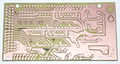
Version 1.4 uses surface mount capacitors and resistors to further cover edge issue cases. As of version 1.3 in order to fit more stuff RAMPS is no longer designed for easy circuit home etching. If you want to etch your own PCB either get version 1.25 or Generation 7 Electronics. Version 1.25 and earlier are "1.5 layer" designed boards (i.e. it's double sided board, but one of layers can easily be replaced with wire-jumpers) that is printable on your RepRap with the etch resist pen method, or home fabbed with toner transfer.
This board is mostly based on Adrian's Pololu_Electronics and work by Tonok. Copper etch resists methods suggested by Vik. Also inspired by Vik's work with EasyDrivers. Circuit design based mostly on Adrian's Pololu_Electronics. Joaz at RepRapSource.com supplied initial pin definitions and many design improvements. Much inspiration, suggestions, and ideas from Prusajr, Kliment, Maxbots, Rick, and many others in the RepRap community.
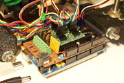
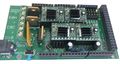
Mendel printed RAMPS wired to Mendel.
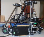
Mendel with RAMPS in enclosure mounted.
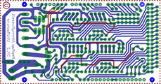
screen capture of 2-sided RAMPS layout
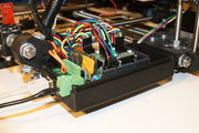
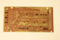
commercially fabbed 2-sided RAMPS wired to Mendel


Features
- It has provisions for the cartesian robot and extruder.
- Expandable to control other accessories.
- 3 mosfets for heater / fan outputs and 3 thermistor circuits.
- Fused at 5A for additional safety and component protection
- Heated bed control with additional 11A fuse
- Fits 5 Pololu stepper driver board
- Pololu boards are on pin header sockets so they can be replaced easily or removed for use in future designs.
- I2C and SPI pins left available for future expansion.
- All the Mosfets are hooked into PWM pins for versatility.
- Servo style connectors are used to connect to the endstops, motors, and leds. These connectors are gold plated, rated for 3A, very compact, and globally available.
- USB type B receptacle
- SD Card add on available -- Available now made by Kliment - Sdramps
- LEDs indicate when heater outputs on
- Option to connect 2 motors to Z for Prusa Mendel
<videoflash type="youtube">0k_KArg_sgA</videoflash>
Voltage and current notes
Standard RAMPS has a 5A PTC fuse that runs the Arduino Mega, the stepper motor drivers, and the D10 and D9 outputs. This PTC fuse is rated for a max of 30V, however other components on the board are rated for lower voltages, so care should be taken when using any voltage >12V.
Standard RAMPS has a 11A PTC fuse that runs the D8 output. This PTC fuse is rated for a max of 16V.
RAMPS was developed with 12V systems in mind, but it is possible to run it at 24V with various precautions. Most RAMPS boards will happily run at 13.8V or slightly higher with no modification. It is not recommended to exceed 15V for a standard setup, especially if you've bought your board from a cheaper supplier who may have used lower spec components than are recommended.
Notes:
- Some variants of RAMPS have real fuses in place of the PTC fuses (eg: GRRF RAMPS). The max current limits will of course be different.
- Many PSU's overestimate their max current capability. The max current you require will depend on all your components and the voltage you run them at. For a standard RAMPS board, running a machine with a heated bed, your PSU should generate 12V at >16A (20+A is better, as some PSU's overestimate their capabilities).
Safety Tip

|
Once you start putting electricity into your RepRap - even at just 12 volts - you have to take basic, common sense precautions to avoid fires.
Just in case these fail, test your workshop smoke detector. Don't have a smoke detector? Get one! |
Support
The primary channel for RAMPS support is the RAMPS Forum
Build and Use
See the page that corresponds with the version you are building RAMPS1.4,RAMPS1.3 or RAMPS 1.2
Ingredients
Schematic
Current schematic shown. For older versions click the image. Click again for full image.

Source
| FILE ID# | TYPE | DESCRIPTION | DOWNLOAD |
|---|---|---|---|
| File:ArduinoMegaPololuShield.zip | Eagle Files | These are the files you need to make the board.(Use the File: link to the left to access older versions of the file.) | media:ArduinoMegaPololuShield.zip |
| File:RepRapjr.lbr | Eagle Libraries | The components used in this board are here. see Eagle_Library | media:RepRapjr.lbr |
Showcase
printed on a RepRap Mendel with the etch resist method Using_cad.py
attempt at printing labels with sharpie
Two-sided PCB Built v1.0
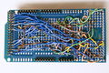
messy back of the first prototype of RAMPS -- built on a generic megaproto shield with point to point wiring, rather than a custom RAMPS PCB
RAMPS with standard pin headers


Change Log
- 1.4 August 4, 2011
- Changed capacitors and resistors to surface mount components
- Added LEDs to mosfet outputs
- Added bulk capacitors for each stepper driver
- Added pull up resistors to enable to override the Pololu drivers default enabled state
- Added mosfet gate resistors
- Added pull-ups for I2C
- Servo1 connector moved to pin 11 to free 7 for ADK
- Fixed thermals
- Servo 5V supply is only connected to VCC if a jumper is added
- Reset switch changed for small footprint
- Moved Aux conectors around a bit and increased board size ~0.1"
- Added some space around Q3 for a small heatsink
- 1.3 May 13, 2011
- Added 5th stepper driver socket
- Added 3rd thermistor circuit
- Added Heated bed circuit w/ 11A PTC fuse, changed to 4 position pluggable input jack to accommodate additional current
- Increased board size to 4"x2.32"
- Pin order on heater outputs changed
- Increased spacing increased to accommodate different connectors
- Added connectors for optional 2 motors on Z driver
- Added connector for PS control
- Improved expansion connector layout
- Moved LED towards corner and added resistor to LED circuit
- No longer optimised for home etching :(
- License changed to GPL v3 or newer
- v1.2 January 04, 2011
- Added 0.1" motor connector to RAMPS for each driver (motors no longer have to be connected on top of stepper drivers)
- Added breakouts for serial and I2C
- Changed extra power and pin headers around for easier connection to extra boards.
- Lost most extra analog breakouts
- More silk screen and bottom layer fixing
- v1.1 September 30, 2010
- Replaced power barrel jack with plug-able screw terminal
- Added jumpers to select micro-stepping on stepper driver boards
- Added debug LED
- Changed mosfet pins to be compatible with FiveD firmware
- Reduced number of 100uF capacitors to 1
- Added 100nF capacitor to 12V input
- Put auxiliary 12VIN and GNDIN pads in a straight line
- Silk screen and bottom layer cleaned up
- v1.0 Original RAMPS PCB design
- v0.1? Point to point wired Arduino MEGA Prototype shield
How to get it
Below are knwn suppliers for the RAMPS board. Note that these are not certified sellers and should not be considered an official recommendation. As it is such a popular board it's been replicated and resold by many of the providers below. As with all reprap electronics, caution is advised when ordering parts to ensure they are safe and from a reputable supplier.
Bare PCB & Components
- Think3dPrint3d
- Ultimachine
- ReprapSource
- XYZ-Printers
- Reprapworld
- RepRapDiscount
- NorcalReprap.com
- Makemendel
- opensourcehardware
Fully assembled board
- Ultimachine RAMPS Original Developer
- Austrian Reprap
- Aus3D
- eMotion Tech
- RobotDigg
- RepRap Z eBay
- Charlie's 3D Technologies
- GADGETS3D.com
- Fabster3D Ebay
- SainSmart
- MakerFarm
- electronic things GmbH
- Brupje
- XYZ-Printers
- MixShop
- A2APrinter
- BCNdynamics store
- Moebyus Machines
- Kitprinter3D
- Impresoras3DLowCost
- 2PrintBeta
- Reprapworld
- RepRapDiscount
- Create3D
- SeeMeCNC
- UltiBots
- NorcalReprap
- RepRap.me
- rp3d.com
- 3D Printer Czar
- Prototyp3d
- Replicator Warehouse
- DIY-India.com
- Cubic-Print
- PrototypeShop
- Thingibox
- Makemendel
- Opensourcehardware
- StaticBoards
- NIOZ (Ru)
- Garage Days 3D (Esp)
- Createc 3D (Esp)
- Threed (Mexico)
Troubleshooting
- Check List
- RAMPS shield firmly seated on Arduino MEGA
- No stray wires/metal to cause short
- All connections firmly seated, screws tight
- Power connection oriented correctly, connected to RAMPS shield (only USB is connected to MEGA)
- Thermistor connected to T0
- Firmware uploaded
- Stepper driver potentiometers to a sane setting (maybe 25% from CCW to start, adjust to enough power to drive axis + not overheat)
- Heater wires properly connected
- Power supply functioning properly
- Cannot connect?
- Verify firmware and host software baud rate matches
- Disconnect USB, reconnect, and retry
- It may be a problem with the software you're using (repsnapper). Try using pronterface.
- Stepper motor getting too hot?
- Adjust the potentiometer (small screw) on the stepper driver in question by rotating the screw counterclockwise to decrease the current going to the stepper motor.
- My fan is not working.
- If you have RAMPs 1.3+ and sprinter firmware (set with the default pins for RAMPs 1.3), try attaching the fan to D9 output.
- In pronterface, the fan can be turned on by using the M106 command and turned off with M107.
- Hot end/heated bed not working.
- Check resistivity by disconnecting from RAMPs and measuring with multimeter
- Check that host software obtains readings from thermistors
Stepper Driver Testing
If you are not sure whether you have a problem with your RAMPS or the stepper drivers you can test that the driver is getting the power and signals it needs to work.
- Stepper motors getting too hot?
- Adjust the potentiometer (small screw) on the stepper driver by rotating the screw counterclockwise to decrease the current going to the stepper motor.
Use a meter of some sort to test the signals at one of the motor drivers. Be careful not to short anything out. You can use a (-) pad in AUX-1 for ground and test the voltage on VMOT, VDD, EN, STEP, and DIR. If all of these are working correctly then the stepper driver is likely bad.
                    High(5V) when disabled, Low when enabled  EN-|     |-VMOT  12V (or voltage at 5A side of input power connector
                                              Set by Jumper  MS1-|     |-GND 0V
                                              Set by Jumper  MS2-|     |-1A     ---------------| <Motor Coil A
                                              Set by Jumper  MS3-|     |-2A     ---------------|____
                                     Not used (tied to SLP)  RST-|     |-1B      -----------------/  |  <Motor Coil B
                                     Not used (tied to RST)  SLP-|     |-2B      -------------------/
                                  Pulse High for each step  STEP-|     |-VDD  5V
Switches between High and Low when driven direction changes  DIR-|     |-GND 0V
Known issues and limitations
Overheating 5V regulator on the Arduino Mega
Unless you provide external 5V power or provide 5V through USB cable, the regulator on the Arduino supplies 5V power to the Arduino, the RAMPS (which uses very little) and anything else connected to it. With nothing else powered from the RAMPS, the voltage regulator will run quite warm but not overheat (in tests, I was even able to turn up the input voltage from 12V to 15V without overheating it). With a 20x4 LCD connected, it's still OK with 12V input. However, if you power a servo or a graphic LCD from the RAMPS, then you will almost certainly overheat the voltage regulator. The usual symptom is that the system will not work unless it is connected to a PC via USB. Or the system may work for a few minutes, hours or days, then fail.
Workarounds include (a) removing D1 on the RAMPS and providing external 5V power to the Arduino/RAMPS; (b) driving the backlight of the graphical LCD from 12V through a series resistor instead of from 5V (a 120 ohm 1W resistor is about right for 12864-type displays), (c) using an Arduino variant with a more powerful voltage regulator (e.g. Taurino), (d) replacing D1 by 3 or 4 diodes connected in series.
Overheating bed heater MOSFET
The STP55NF06L mosfet is not really adequate to drive a 10A heated bed without a heatsink, so on boards supplied without a heatsink it runs very hot. This is often exacerbated by the previous issue (overheating 5V regulator), which causes the voltage on the 5V rail to be significantly lower than 5V and insufficient to turn the mosfet fully on.
Workaround: either add a heatsink, or (preferably) replace the bed heater mosfet (Q3) by a better type such as IRLB8743PBF or IRLB3034PBF. Also check that the voltage on the 5V rail is close to 5V, preferably at least 4.75V.
USB data rate fails to keep up with the printer, resulting in slow, poor-quality prints
This is due to the lack of a true USB port on the Arduino Mega, which uses USB-over-serial instead, and the consequent lack of driver-level flow control. As a result, flow control has to be done at application level by the host program waiting to receive "OK" after sending each command. General purpose host operating systems such as Windows and Linux cannot do this efficiently. Some host programs and operating system combinations work better than others, but this issue has even been reported by some users running Octoprint on a dedicated Raspberry Pi host.
Workaround: print from SD card instead of over USB.
Melting heatbed connectors.
Some users have reported issues with the screw terminals for the heatbed melting or catching fire. This is due to a design flaw, with the components used not being rated for the amount of power most heatbeds will draw. It may also be caused by the screws in the terminal block working loose. Stranded-core cables should not be tinned before inserting them into the terminal block, because the solder will creep under the heat generated by the high current.
A commonly recommended fix which reduces the load on your RAMPS board significantly is a standalone MOSFET pcb. This allows you to plug both your heatbed and heatbed power source into the MOSFET pcb. You then connect it to where your heatbed would've plugged into your ramps board.
By offloading the power requirements to a higher rated MOSFET, it significantly reduces the load on the RAMPS board, and is a relatively cheap and easy upgrade to make. The MOSFET pcbs are widely available, with sellers on AliExpress, BangGood, Amazon and Ebay.
Q&A
- What power supply you recommend for your ramps board. I have just finished assembly and looking at the diagrams for a pc power supply and wondering about the separate amperages for the extruder and heated bed. Can they be higher amps without damage?
Yes, the power supply being capable of more amps than required is the desired configuration. The current shown are the max supported by RAMPS and is the minimum the power supply should be capable of. It is also OK to have both of the inputs on RAMPS connected to one PSU with enough capacity. If you are not using a heated bed the entire thing can run off the 5A side (D8 will just not work).
- I got a RAMPS V1.3 as part of a kit, but it doesn't have any installation instructions - just a schematic. Can you point us to a good tutorial for connecting everything? (i.e. stepper motors, opto flag pcb's, power, data, etc) Some of it (like the single USB port) is obvious, but some of it isn't.
See RAMPS1.3 for instructions for version 1.3. There is a version navigation bar at the top of the RAMPS pages that allow you to jump to a specific versions instructions. There is a very helpful graphic under Final Check section.
- For RAMPS V1.3 the power section of the schematic shows several places with GND/12V (C4/C6, X4-2/1, X4-4/3, VCC/D12). Which one is the GND/12V from the power supply? Is it the round power plug like a laptop power plug? Also, is the outside of that plug GND while the inside is +12V? My kit came with a note warning not to reverse the input power or it would cook the board . . . and a plug adapter with no labels that can be installed either way.
See the connecting power section of your version's page. The round plug is on the Arduino MEGA and will only power the MEGA. You need to power the green pluggable connector, it should not be reversible and the board should be marked (+) and (-). If for some reason your board is not marked you can follow the diagrams and pictures in the wiki.
- What connectors can I use to attach my own wires to the board? 2 pin 3 pin and 4 pin headers with wires are good and sold, but what if I want to make my own with Dupont terminals and crimps or with JST connectors and crimps(which are cheaper).
Can JST connectors be used, what contact pitch- 1mm or 2mm, will there be enough space on sides on standard RAMPS board?
The pins on the board are on .100" (2.54mm) centers, which is standard configuration. Standard single-row headers are .100" (2.54mm) wide. As long as your connectors are not larger than .100" x .100" (2.54mm x 2.54mm) they will fit.
Sanguinololu
|
English • العربية • български • català • čeština • Deutsch • Ελληνικά • español • فارسی • français • hrvatski • magyar • italiano • română • 日本語 • 한국어 • lietuvių • Nederlands • norsk • polski • português • русский • Türkçe • українська • 中文(中国大陆) • 中文(台灣) • עברית • azərbaycanca • |
- This page describes the Sanguinololu versions 0.7 and newer, including the current versions. For older versions see Sanguinololu_0.6.
Release status: working

| Description | Release Version 1.3a
|
| License | unknown
|
| Author | |
| Contributors | |
| Based-on | |
| Categories | |
| CAD Models | Eagle
|
| External Link |
Sanguinololu is a low-cost all-in-one electronics solution for Reprap and other CNC devices. It features an onboard Sanguino clone using the ATmega644P though a 644, 1284 or 1284P is easily dropped in. Its four axes are powered by Pololu pin compatible stepper drivers. The board is designed to be flexible in its power source, working with a 12V/5V ATX power supply or any 7V-35V power source via the on-board voltage regulator.
Features
- Small design – board is 100mm x 50mm (4" x 2") – barely an inch longer than a business card
- Sanguino clone, Atmel ATmega644P – ATmega1284 drop-in compatible
- 4 Pololu (compatible) stepper driver boards on-board (X,Y,Z,Extruder)
- Supports multiple power configurations
- – Logic and motors supplied by ATX power supply
- – Motors supplied by 5mm screw terminal 7-35V
- – Logic supplied by USB
- – Logic supplied by on-board voltage regulator
- Supports multiple communication configurations
- – FT232RL on-board for USB connectivity
- – USB2TTL header is available for FTDI cable or BlueSMIRF bluetooth module
- 2 thermistor connectors with circuitry
- 2 N-MOSFETs for extruder/heated bed
- Selectable 12v(or supply voltage)/5v endstop voltage
- Edge connectors enabling right-angle connections
- Silkscreen for connectors on both sides of the board, facilitating bottom cable connections
- 13 extra pins – 5 analog and 8 digital – available for expansion and development, with the following capabilities
- – UART1 (RX and TX)
- – I2C (SDA and SCL)
- – SPI (MOSI, MISO, SCK)
- – PWM (1)
- – Analog I/O (5)
- All through-hole components (except FTDI chip) for easy DIY soldering
Derivatives
The Sanguinololu design has spawned several derivatives, including the Teensylu, which replaces the microcontroller with one supporting on-board USB, rendering the FT232RL superfluous, and following on from that the Printrboard, which also has directly incorporated stepper drivers and SD card reader on-board.
Bugs
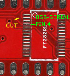
- The USB 5V VBUS is connected to the output of the 5V regulator. This is bad for the regulator and bad for the PC. Some users report the regulator getting very hot (because it is trying to power the PC), other users report the PC giving USB over current errors. Nophead and Nothinman recommend cutting the 5V track to the USB connector. The only downside is the board needs the 12V supply before it will do anything, but who cares?
- An alternate fix for the 1.3a board is to cut the trace between the USB chip pin 4 and C13. This is functionally identical to building a Sanguinololu without the USB port and FT232RL and using an offboard USB-serial cable. The advantage over cutting the 5V trace at the USB connector is that the USB serial port doesn't disappear from the host PC when the printer is switched off, which can anger host software that is still running.
- Another fix that seems to work using Schottky diodes: http://forums.reprap.org/read.php?158,400825
- Another fix is to strip the insulation and shield from the USB cable and cut the 5V wire. This has the advantages that, if the board is powered off, another cable with all wires intact can be used to communicate with the board and it does not require a board modification. The 5V wire can be identified by searching for USB pinouts and can be checked by sticking a needle through the wire insulation to measure conductivity.
- When the bootstrap loader runs during reset and when downloading firmware the motors are enabled due to pull-downs on the Pololus (The enable pins are pulled up by 100K resistors on the Sanguinololu but they are pulled down by 100K on each Pololu). The step pins are floating and this can cause random motor movements. The E step pin is next to E dir pin which the bootstrap thinks is an LED to be flashed. Crosstalk can cause the extruder to spin when firmware is being loaded. This is not good as it will be cold, so could damage the hot end. Nophead recommends changing the enable line pull ups (R7 and R8) to 4K7 to ensure the motors are disabled until the firmware enables them.
- A software fix is to use the the Gen7 boot strap that does not flash the non-existent LED.
- The pads and traces on the board are not robust enough to handle the high current involved when controlling the heated bed with the sanguinololu's dedicated mosfet. If left as is, the board will heat up in this area, could be damaged and the plastic connectors discolored. To fix, simply add a direct current path by way of (preferably insulated) wire from the 12v input to the 12v pins on the Heated Bed (HB) connector; from the center pin of the HB mosfet to the two ground pins on the HB connector; and from the ground pin on the mosfet to the ground input of the board (probably the ground side of the 12v connector). Find the appropriate traces using continuity check or resistance mode on your multimeter, and check after to ensure you didn't create a short between any of these components in the process. It would be prudent to check for shorts before starting so you don't waste effort trying to fix a short you think you just created but was already there before you applied this fix. To understand this fix, pretend that no traces exist between the high current pathways of the 12v input and 12v pins of the HB connector; the ground input and the ground pin on the mosfet, and the center pin of the mosfet and ground pins on the HB connector. Assume you must create these pathways, then do so!
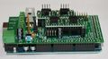
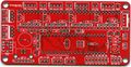
Schematic & Board Images
1.3b2 Top
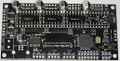
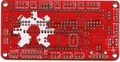
1.3b2 Bottom
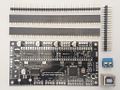
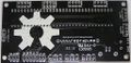
1.3b2 With thru-hole components unassebled


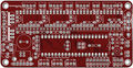
1.3a Top
1.3a Bottom
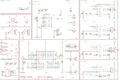
1.3a sch


Reference Renders
(Click to view older versions.)
Board top
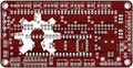
Board bottom
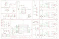
Board schematic


Where to get it
You can get the bare pcb, a complete kit or assembled boards at:
- Blomker Industries (1.3a assembled, 644P)
- RepRap.me (1.3b2 kit, 1284P)
- SainSmart (1.3a assembled, 1284P)
- XYZ Printers (1.3a bare pcb, kit, 644P)
(If any other resellers have this available, please add to this section.)
You will also need four Pololu stepper drivers or compatibles like the StepStick.
EAGLE files, parts list
Schematics, board layout, images: https://github.com/mosfet/Sanguinololu/tree/master/rev1.3a
Parts list: https://github.com/mosfet/Sanguinololu/blob/master/rev1.3a/parts.txt
| |
Caution This parts list is reported to be both incorrect and incomplete. The IC should be a 644P, not simply a 644. Check the assembly instructions (below) for the parts needed. Also, ensure to buy 1/4 watt resistors, since larger ones won't fit the PCB. |
Assembly Instructions
For users soldering a 1.3a board:
- You'll have a 2-pin male header and jumper shunt to solder for the AUTO-RST function of the FTDI. This is located right above the ATmega chip. TODO: Get pics and incorporate this into the instructions below.
A step-by-step build guide to the 1.2 PCB is available with low, medium and high resolution images.
Modifying Older Boards (from Version 1.1 and 1.2 to Version 1.3a)
To modify a v1.1 PCB to make it (electrically/firmware) equivalent to a v1.2 PCB, the image below and this drawing show the track cuts and additional wire links required.

| |
Note Wire bridges are now used in place of R7 and R8 on v1.2 and v1.1 boards modified to v1.2 electrical/firmware equivalence. |
To create a 1.3a equivalent PCB from a v1.1 board modified as above, or a standard v1.2 board, the following changes are required:
- Mount C7 in a socket so that it can be unplugged - as per Adrians Prusa Notes.
- Adding two 100k pull-up resisitors, one each between 5V and Pin 20 and Pin 35 of the ATmega chip.
| |
Caution As at 2011-09-12 the above mod (from v1.1 modded or v1.2 standard to v1.3a) has yet to be functionally tested/verified. |
Introduction
Gather the tools you will need to perform through-hole soldering, and if you opted for the on-board FTDI IC, some SMT soldering as well. Soldering pencil and/or iron, solder, and most importantly: flux! I can't stress how much easier flux makes soldering the SMT device.
Carefully inspect your board for defects. Look for strange connections between traces. Become familiar with the locations of devices from the back as well as the front.
Gather your components and ensure you have the complete parts list for your selection. This photo shows enough parts for two Sanguinololus - one with ATX connectors and the other with screw terminal and voltage regulator.

Soldering the FTDI USB to serial IC
Install the FT232RL FTDI IC. Note the orientation of the silkscreen. Solder using your favourite SMT soldering method. The board pictured was tinned from the fabrication shop. After applying flux to the pads, and carefully placing the chip, it was easily soldered by touching the tip of the soldering pencil to the end of a pad to tack the chip down, and then on the pin itself to flow the solder correctly. If you're not sure you want to tackle the SMT soldering, boards are available with this IC pre-soldered. An alternative is to use a USB to TTL-converter instead of this IC.
Parts:
IC100 FT232RL FT232RLSSOP


Next install the FT232RL support components, minding the polarization of the electrolytic capacitor (C16).
Parts:
 J1       USB              USBPTH
 C7       0.1uF            CAPPTH2
 C8       0.1uF            CAPPTH2
 C11      0.1uF            CAPPTH2
 C15      0.1uF            CAPPTH2
 C16      4.7uF            CAP_POLPTH2

Now is a good time to test the FTDI chip. Plug a USB cable into the port. The device should show up as a COM port or a TTY device and allow itself to be opened. If you temporarily connect the 'TX' and 'RX' pins on the USB2TTL port on the back of the board anything you type in your terminal application (such as PuTTy) should be echoed back to you. Be sure that your jumper doesn't short to the case of the USB connector just below it and fool you into thinking you have a problem when you do not.
Note that when you have finished the assembly and want to connect to the board using your printer software, then if you are using Windows XP you will need to load the FTDI drivers from the FTDI Virtual Com Port Drivers webpage. As of (2015?) FTDI made driver installation noticeably easier on a machine running Windows. Only one Windows setup executable file should be required to be downloaded and installed, though it is still possible to do it manually by downloading the CPU dependent (32 or 64-bit) CDM zip archive from the same webpage. After the drivers are installed by either method, on first connecting Sanguinolou via USB cable to a computer running Windows, the FTDI chip will be recognized and the the driver install process will be completed.
Soldering the Sanguinololu core
Next, solder the female headers, making sure they're straight and completely seated on the PCB. Where two lengths of header strip are placed so they join in the middle, they may be fractionally too long to lie flat on the board at the join. In this case, carefully file off some of the plastic at the adjoining ends until they fit together in the space available.
Parts:
4x Female Pin Header 16 Pin

Solder MS1, MS2 and MS3 jumper headers. I find that it is easier to solder the 2-pin header if the jumper shunt is installed. Ensure they're completely seated and straight. Leaving the jumper shunt in place will pull the MS pins high, i.e. set the Pololu controller to sixteenth step resolution. This turned out to be the appropriate setting for my out-of-the-box firmware. If your motors move erratically, check these.
Parts:
 12x Male Pin Header 2 Pin
 12x Jumper Shunt

Install the LED current-limiting resistor and the MS1 pull-down resistors (MS2 and MS3 have internal pull-down resistors).
Parts:
 R1       1k (1.5k)        RESISTORPTH1
 R2       100k             RESISTORPTH1
 R3       100k             RESISTORPTH1
 R4       100k             RESISTORPTH1
 R5       100k             RESISTORPTH1

Solder the driver decoupling capacitors. Before soldering, bend the leads to the side so the capacitor lays down. Mind the polarization!
Parts:
 C1       100uf            CAP_POLPTH1
 C2       100uf            CAP_POLPTH1
 C3       100uf            CAP_POLPTH1
 C4       100uf            CAP_POLPTH1

Install the thermistor high pass RC filters. Mind the polarization of the capacitors. Install the MOSFET pulldown resistors.
| |
Important Note If you're building a Sanguinololu 1.3a, install 100K resistors as R7 and R8. If you're building a Sanguinololu 1.2, do not install resistors in R7 and R8. Instead, replace them with wire jumpers - for example, two clipped leads from a previously soldered part. |
Parts:
 R6       10k               RESISTORPTH1
 R11      10k               RESISTORPTH1
 R7       100k - 1.3a only! RESISTORPTH1
 R8       100k - 1.3a only! RESISTORPTH1
 C9       10uF              CAP_POLPTH2
 C10      10uF              CAP_POLPTH2
 R9       4.7k              RESISTORPTH1
 R10      4.7k              RESISTORPTH1

Install the DIP socket and ceramic resonator. Before soldering, bend the resonator leads so that it lays down within the dip socket. It doesn't matter which way round it goes.
Parts:
 DIP-40   SOCKET
 Y1       16MHz 22pF       RESONATORPTH

Install the two ceramic caps for the ATmega and the reset pull up resistor.
Parts:
 C14      0.1uF            CAPPTH2
 C13      0.1uF            CAPPTH2
 R12      100k             RESISTORPTH1

Solder the MOSFETs, the large charge capacitor, the reset button, and the power LED. The power LED's negative lead is on the flat side, or the shorter lead. The negative lead goes to the left in the picture.
Parts:
 Q1       RFP30N06LE       MOSFET-NCHANNELPTH2
 Q2       RFP30N06LE       MOSFET-NCHANNELPTH2
 C12      1000uF           CAP_POLPTH4
 S1       RESET            TAC_SWITCHPTH
 LED1     POWER            LED3MM

ATX power supply
If you are using the ATX power supply, install those connectors.
Parts:
 ATX1     ATX-4VERTICAL    ATX-4VERTICAL
 HDDPWR   5v/12v           DRIVEPWRVERTICAL

| |
Important Note It has been suggested (thanks Kliment & tonokip) that the 5V coming from the ATX power supply may not be as stable at 5V as one could hope. It would be better here instead of using the 4-pin hard-drive connector to use only the 4-pin ATX connector and the voltage regulator. The 4-pin ATX connector will still provide enough power for the board. One could even forgo the voltage regulator and power the logic side of the board solely by USB. |
Voltage regulator & screw terminal
If you are using the voltage regulator and screw terminal, install those parts now. Note the orientation of the LM7805. Label the screw terminal with a felt tip marker which side is positive and which is negative. On later versions of the board the screw terminals mount at right angles to the way shown so the wire they connect to comes out parallel to the USB lead.
Parts:
 IC1      LM7805           VREG
 C5       0.33uF           CAPPTH2
 C6       0.1uF            CAPPTH2
 JP23     SCREW            M025MM

Connectors
Finally, solder the motor, end stop, thermistor, and bed/tip connectors. Optionally solder the 12V (or supply voltage) connectors along the top of the board, and the ISP 6-pin header (for programming the ATmega).

For speeding up the soldering of the connectors in case you use pin headers, you can use longer strips and just snip the unused positions, like this (top strip left, endstops right), resulting in a board as shown:


Alternative build, using IRLB8743 Mosfet
See [Create3D.com.au],
Step 1
Solder FTDI chip on back of PCB,
4 X 0.1uF (100nF) capacitors to C7, C8, C11, C15
1 X 10uF capacitor goes in C16, change from Sanguinolu, square marking notes positive anode
1 X USB hub
attach USB to computer and confirm the FTDI chip is read
Step 2
R1 1k or 1.5k
R2 100k
R3 100k
R4 100k
R5 100k
R6 4.7k (create3D)
R11 4.7k (create3D)
R7 100k
R8 100k
R9 4.7k
R10 4.7k
Capacitors, note polarity
C1 100uF, bent flat
C2 100uF, bent flat
C3 100uF, bent flat
C4 100uF, bent flat
C9 10uF
C10 10uF
C6 100nF, optional, if LM7805 is used
Step 3
2 Pin Jumper Shunt X12
32 Pin Header X2
Step 4
Y1 16Mhz 22pF Ceramic Resonator, bend it flat, label up
C13 100nF
C14 100nF
R12 100k
Dip 40 Socket, note alignment to co-ordinate with chip
optional 2X1 header
Step 5
Q1 MOSFET
Q2 MOSFET
C12 1000uF
S1 Tact Switch
LED1 Green, 3mm, the - lead goes left, the + lead is nearest the corner hole
INCOMPLETE
Missing IC1 LM7805
Missing C5 0.33uF, right of LM7805
Missing power
Missing headers
These all go depending on power and pin layout decision.
EXTERNAL
Pololus
When you solder the pin strips onto the Pololus you will find it easiest to insert the strips in the appropriate place in the Sanguinololu. Then just drop the Pololu boards on top and solder them in place. Check the polarity is correct - don't trust checking it against an image on this wiki. Make sure that pins 1a, 1b, 2a, & 2b are closest to the edge of the board. You can then unplug them later if you want.
Endstops
Mechanical micro-switch endstops are recommended for their simplicity and reliability. It is recommended to wire the switch terminals Common (C) and Normally Open (NO) to GND and SIG on Sanguinololu (the two outside pins on the endstop connectors). Ensure you set Endstops_Inverting to true in your firmware.
If you are using optical endstops or proximity sensors (or other endstops that require power) you can use either 5V or 12V (or supply voltage) depending on what endstop device you want to use. This is selected by soldering a little link labeled "Stop Volt" on the back of the board. With the text the right way up, joining the left pad to the middle one gives 12V (or supply voltage), right to middle gives 5V. Take care not to short all three together.
Fan
The 1.3a board does not have a separate PWM output for a 12 V cooling fan. You can adapt a spare 5 V output with a firmware edit and an external power transistor circuit. Example here.
Software
| |
Caution The detailed instructions in this section are outdated. They apply to the ATmega644P and old Arduino IDEs only. For more recent instructions, refer to the Arduino IDE Support page for the Gen7 electronics. This includes downloads, installation instructions and bootloader upload instructions. It will show you how to handle the ATmega644, ATmega644P and ATmega1284P and how to make use of recent Arduino IDEs. The Gen7 Arduino IDE support package works for a Sanguinololu just fine. |
To run the printer, you'll need host software on your computer to send instructions to the Sanguinololu (unless you equip it with an SD card reader and your firmware supports printing direct from SD card). Software choices are listed at RepRap_Options#G-code_sender.
Additionally, you need two pieces of software on the Sanguinololu itself:
- A bootloader, to facilitate uploading a firmware over the serial port. Most RepRap vendors deliver ATmegas with a bootloader already installed. No matter which firmware you prefer, there is no need to replace the bootloader as long as it works.
- A firmware, which contains all the logic to make your printer move according to the G-code commands sent to it.
Bootloader
If you can already upload a firmware over the serial port or prefer to upload your firmware with a programmer, you can skip this step. Bootloader and firmware are entirely independent of each other.
For your Sanguinololu to accept firmware over the USB connection you first need to burn the bootloader (coming with Gen7 Arduino IDE Support) to the ATmega. There are several ways to accomplish this, detailed under AVR Programmers.
If you want to program the bootloader manually (ie if you don't own an AVR programmer) use this file for the 1284P: [1]
Fuse Settings
The fuses for the ATmega must be changed from the default factory settings to disable JTAG.
Symptoms of incorrect fuse settings:
- X axis only moves in one direction.
- Endstops do not work.
644P Fuse Settings
The settings come from the bootloader's boards.txt file.
Example using avrdude and usbtiny.
avrdude -B 8 -patmega644P -c usbtiny -U lfuse:w:0xFF:m -U hfuse:w:0xDC:m -U efuse:w:0xFD:m
1284P Fuse Settings
avrdude -p atmega1284p -c stk500v1 -b 19200 -V -e -U lfuse:w:0xD6:m -U hfuse:w:0xDA:m -U efuse:w:0xFD:m -U flash:w:ATmegaBOOT_168_atmega1284p.hex:i
9/19/15: The hfuse setting above sets the frequency incorrectly IMO (I consulted the ATmega datasheet, but would someone double check?). I set it to D6 for a ceramic resonator, slowly rising power.
Checked as requested: The lfuse setting controls the oscillator, not hfuse. The only functional difference between your setting D6 (nominally for ceramic resonator) and the Gen7 setting F7 (nominally for crystal oscillator) is that D6 only allows 258 clock cycles for the resonator to stabilise on start-up, while F7 allows 16000 clock cycles. Furthermore, note that the ATmega data sheet specifies that D6 "should only be used when not operating close to the maximum frequency of the device, and only if frequency stability at start-up is not important for the application". In all cases (ceramic and crystal), F7 should be at least as reliable, the only downside being a ~1 ms delay in start-up time. For simplicity, I would suggest using the Gen7 settings (which I have confirmed working) in all cases. Given the large degree of confusion surrounding fuse settings, I will edit this page to remove all the conflicting information and settle on the Gen7 settings in a few days unless I see an objection.
Firmware
You will need to upload a RepRap firmware to your Sanguinololu once the bootloader has been burnt. You can do this using the Arduino IDE (v0022, 1.0 has issues with the Arduino library coming with the Sanguino extensions). Compatible firmwares include:
- Sprinter The instructions in the readme are outdated. Use the Gen7 Arduino IDE package as noted above. Check the Configuration.h to ensure that Sanguinololu is selected as your board: board 62 for v1.2 and newer, board 6 for v1.1 and older.
- Marlin
- Teacup In older Teacup versions, copy config.sanguino-xxx.h to config.h, in newer Teacup versions choose board.sanguinololuxxx.h as board. "xxx" stands for your Sanguinololu version.
- Repetier-Firmware
Troubleshooting
stk500_recv
avrdude: stk500_recv(): programmer is not responding
Possible causes:
- Arduino IDE / bootloader mismatch.
- Wrong baud rate (the bootloader requires its own baud rate which doesn't necessarily match the firmware's baud rate).
- Hardware issue.
stk500_getsync
avrdude: stk500_getsync(): not in sync: resp=0x00
avrdude: stk500_disable(): protocol error, expect=0x14, resp=0x51
Workaround
To resolve for boards older than Rev 1.3a, hold the reset button on your Sanguinololu for about 10 seconds. While still holding the button, try to upload the firmware again. Let go of the reset button as soon as the Arduino IDE reports, "Binary sketch size: ###### bytes (of a 63488 byte maximum)". The firmware should now be accepted.
Permanent fix
A fix was added in Rev 1.3a. If unpopulated, solder a 2-pin header to the "Autoreset Enable" jumper labeled AUTO RST on the silkscreen. This is located between the Z stepper motor socket and pins 8-10 of the ATMEGA644P socket. In addition, you should also set your Virtual COM port parameter "RTS on close" to ON. Adding the jumper allows the PC to reset the Sanguinololu board during programming and interactive sessions. Removing the jumper allows the printer to run in standalone mode; that is, the board will not reset mid-print when the PC is disconnected or reconnected.
Other possibilities
Another thing to check is the baudrate in "hardware/Gen7/boards.txt". Gen7xxx.upload.speed should be 115200. The Arduino IDE will not see changes to this file until it is restarted.
Another item to check is whether virtual com port drivers are installed correctly. Make sure you see "USB Serial Port" under the heading "Ports (COM & LPT)". If you see a USB driver in the "Other" category with a question mark, you need to manually select the driver for the FTDI chip with drivers from the website.
Another stk500 error
avrdude: stk500_recv(): programmer is not responding
IRC was very helpful asked me to edit the sanguino boards.txt and change the programmer type to 'arduino' instead of 'stk500'. Which gave me:
avrdude: Can't find programmer id "arduino"
Then I was to check if I had any files in, which I do. After that it spat out:
avrdude: error: no usb support. please compile again with libusb installed.
Solution
As I already had avrdude installed, I just moved the old avrdude binary that came with Arduino 0018 and made a symlink from /usr/bin/ to where the old binary was:
mv ~/tmp/arduino-0018/hardware/tools/avrdude ~/tmp/arduino-0018/hardware/tools/avrdudeOLD
ln -s /usr/bin/avrdude ~/tmp/arduino-0018/hardware/tools/
Final Check
Pololu drivers current limit configuration
Before going further, it's very important to configure the current limit of your Pololu drivers or you'll risk burning out your stepper motors or the Pololus. This should be done with the board powered but before connecting the motors. Always power off before connecting or disconnecting the motors.
First of all, note that there are usually two types of NEMA 17 motors :
- high voltage stepper motors, that work usually on 12 to 14V, the working current is usually below 1A. These don't work well with microstepping chopper drivers and are not recommended.
- low voltage stepper motors, that work usually on 2 to 4V, the rated current is usually over 1A.
It is safe to drive low voltage stepper motors at a much higher voltage because the Pololu A4988 has current limit functionality. The higher the voltage applied compared to the motor's rated one, the faster your stepper motor can run. The A4988 chip can only provide up to 2A per coil so choose your stepper motor accordingly.
A good starting point for the current is <math>0.7</math> times its rated current. This is typically ~1A with the recommended 1.68A NEMA17 motors and that is about the maximum current the Pololu can deliver without a heatsink or a fan. Note that the rated current of a motor is usually that which gives an 80C temperature rise, which is too hot for plastic brackets, hence the reason to under-run them.
The recommended way to set Pololu drivers current limit is to measure the voltage at the Vref test point. The A4988 datasheet gives all the required information to configure the current limit of a Pololu driver :
The peak current <math>I = \dfrac{V_{REF}}{8 \times R_S}</math>
where <math>R_S</math> is the resistance of the sense resistor (<math>\Omega</math>) and <math>V_{REF}</math> is the input voltage on the REF pin (V).
On the Pololu driver board, the <math>R_S</math> value is <math>0.05 \Omega</math> and the <math>V_{REF}</math> can be measured on the test point shown below, or the metal wiper of the pot. <math>I</math> is equal to the recommended current limit for your stepper motor multiplied by <math>0.7</math>. Thus you can determine the <math>V_{REF}</math> you'll need with:
<math>V_{REF} = I \times 8 \times 0.05 = 0.4 \times I</math>
For example if your motor is rated 2.8V at 1.68A, you adjust the pot so that you measure the following value for <math>V_{REF}</math> :
<math>V_{REF} = 1.68A \times 0.7 \times 0.4 = 0.47 V</math>

Note that the StepStick pin compatible driver has 0.2<math>\Omega</math> sense resistors and the current is limited to a little over 1A with <math>V_{REF}</math> = 1.7V.
Symptoms of not enough current are skipping steps and poor microstepping linearity. Too much current will cause the motor or the driver to overheat. When the driver overheats it shutsdown for a few seconds and then restarts again when it cools. This makes the motor twitch when it is stationary and pause during motion.
See also Pololu's presentation on calibrating/testing the driver boards: [2]
Wiring shematics

Powering Sanguinololu
Your chosen power solution will determine what kind of power requirements will be in play:
Screw terminal: Connect your power supply with at least 7V and at most 30V to the screw terminal. The negative lead is the one closest to the screw hole.
ATX Power Connector: Connect the ATX-4 pin connector. The ATX power supply must also be rigged to turn on when plugged in & the switch is on. This is done by shorting the !PWR_ENABLE pin to ground on the main ATX-20 pin connector. This is usually the green wire shorted to a black wire. I use a staple crammed in the socket, and use the switch on the power supply case to control system power.
Pin Assignments
Chip layout v1.2+                                                      | Tabular format v1.2+              | Tabular format v0.7 - v1.1
                          +---vv---+                                   |                                   |
   e-dir       (D0) PB0  1|        |40  PA0 (AI0 / D31) ext            | e-dir              D0        PB0  | e-dir               D0        PB0
  e-step       (D1) PB1  2|        |39  PA1 (AI1 / D30) ext            | e-step             D1        PB1  | e-step              D1        PB1
   z-dir INT2  (D2) PB2  3|        |38  PA2 (AI2 / D29) ext            | z-dir              D2        PB2  | z-dir               D2        PB2
  z-step  PWM  (D3) PB3  4|        |37  PA3 (AI3 / D28) ext            | z-step             D3        PB3  | z-step              D3        PB3
     ext  PWM  (D4) PB4  5|        |36  PA4 (AI4 / D27) ext            |                                   | step-enable-x-y-e-z D4        PB4
     spi MOSI  (D5) PB5  6|        |35  PA5 (AI5 / D26) !step-enable-z | !hotbed            D12       PD4  |
     spi MISO  (D6) PB6  7|        |34  PA6 (AI6 / D25) b-therm        | !hotend            D13       PD5  | hotend              D13       PD5
     spi  SCK  (D7) PB7  8|        |33  PA7 (AI7 / D24) e-therm        | !step-enable-x-y-e D14       PD6  | hotbed              D14       PD6
                    RST  9|        |32  AREF                           | x-step             D15       PD7  | x-step              D15       PD7
                    VCC 10|        |31  GND                            |                                   |
                    GND 11|        |30  AVCC                           | x-stop             D18       PC2  | x-stop              D18       PC2
                  XTAL2 12|        |29  PC7 (D23)       y-dir          | y-stop             D19       PC3  | y-stop              D19       PC3
                  XTAL1 13|        |28  PC6 (D22)       y-step         | z-stop             D20       PC4  | z-stop              D20       PC4
    ftdi  RX0  (D8) PD0 14|        |27  PC5 (D21) TDI   x-dir          | x-dir              D21       PC5  | x-dir               D21       PC5
    ftdi  TX0  (D9) PD1 15|        |26  PC4 (D20) TDO   z-stop         | y-step             D22       PC6  | y-step              D22       PC6
     ext  RX1 (D10) PD2 16|        |25  PC3 (D19) TMS   y-stop         | y-dir              D23       PC7  | y-dir               D23       PC7
     ext  TX1 (D11) PD3 17|        |24  PC2 (D18) TCK   x-stop         | e-therm            D24  AI7  PA7  | e-therm             D24  AI7  PA7
 !hotbed  PWM (D12) PD4 18|        |23  PC1 (D17) SDA   ext            | b-therm            D25  AI6  PA6  | b-therm             D25  AI6  PA6
 !hotend  PWM (D13) PD5 19|        |22  PC0 (D16) SCL   ext            | !step-enable-z     D26       PA5  |
!step-en  PWM (D14) PD6 20|        |21  PD7 (D15) PWM   x-step         |                                   |
                          +--------+                                   |                                   |
Microstepping Jumper Settings

SD / Bluetooth Adapters
At least two adapters exist for the Sanguinololu using the IO and ISP headers.
- SDSL (microSD card reader)
- Sanguinololu Wireless Adapter (bluetooth and microSD card reader)
Revision History
Rev.1.3b2 by RepRap.me - updated August 19, 2014 This version has no schematic changes from version 1.3a - the bootloader however is changed to reflect the CPU upgrade though your 1.2+ compatible firmware should still work fine. The hardware changes:
- ATX 4-pin Mini-Fit connector were removed so only the 2-pin screw terminal remains
- Solder jumper for endstop voltage selection removed, now fixed to 5 volt rail
- Through-hole MS1, 2 & 3 pinheaders substituted by solder jumpers
- Through-hole enable/disable USB auto-reset pinheader substituted by solder jumper
- Through-hole 16MHz oscillator crystal substituted by equivalent SMD type
- Through-hole Voltage regulator (TO-220 LM7805) substituted by equivalent SMD type
- Through-hole reset button substituted by equivalent SMD type
- 3-pin endstop connector substituted by 4-pin CDROM type (the two center pins are Ground)
- The space between the ICSP/SPI header and the expansion port has been enlarged from 50 to 100 mils
- General optimizations of traces in circuit layout
- FTDI pin header beneath the USB plug were removed
- ATMEGA644P was substituted by ATMEGA1284P to give more space for firmware (more functionality: SD-cardreader, display etc.)
- Change of bootloader, now uses ATmegaBOOT_168_atmega1284p.hex which can be found on code.google.com
The resulting PCB now mostly consists of SMD components thereby facilitating easier production
Rev 1.3a
Version 1.3a has no firmware changes -- the pin assignments remain the same and v1.2-compatible firmware should work fine. The hardware changes:
- Removed the Molex HDD connector in favor of using the voltage regulator - some power supplies give a dirty 5V signal when there is no motherboard load, so it's better to just use the power supply's ATX+4 connector and the 5V voltage regulator.
- Added a jumper to enable/disable USB auto-reset. This way if you're printing from an SD card using SDSL you can disconnect your USB and reconnect it without interrupting a print.
- R7 and R8 are now 100k pull-up resistors on the stepper-enable lines. This ensures the stepper motors stay disabled and don't move while uploading new firmware, rebooting, etc. The current limiting resistors for the FTDI are gone.
- There is an extra Z-motor header for Prusa Mendel.
Rev 1.3 Custom modification for WebSpider -- it spaces the hottip and hotbed connectors better. No firmware changes.
Rev 1.2 Updated June 15, 2011.
While v1.1 is completely functional, there were some requests from users for pin assignment changes. Version 1.2 implements these firmware changes.
- Z-Enable is now on its own pin.
- PWM devices have been moved to OC0 and OC1 freeing up OC2 for internal timing.
- The expansion port is now a pin shorter -- the Z-Enable feature ate an analog pin here.
Version 1.2 still includes the footprint for the Molex HDD connector, though it may be wise to disregard it and always install the 5V regulator as not all ATX power supplies' 5V lines are stable and clean. NOTE: On the bottom side of the board, the footprint for the Molex HDD connector is backwards (beveled edges facing towards the edge of the board). Take care if soldering from the bottom side of the board to orient the HDD connector with the beveled edges facing towards the center of the board, as shown on the top side silkscreen.
Rev 1.1
Corrected silkscreen mistake. Added open hardware logo.
Rev 1.0
Release revision: tighter DRC rules and rotated screw terminal footprint. There is one tiny mistake on the 1.0 board: the leftmost pin on the expansion header labelled 5V is actually 12V (or supply voltage).
Rev 0.7
Added more pins to the expansion header, made I2C and SPI available for use. Combined all stepper motor enable nets into one pin.
Added footprints for voltage regulator for those wanting to use laptop power brick, etc. The vreg component footprints are hidden under the ATX power supply for space saving and to prevent both from being in use.
Enabled USB bus power for logic side.
Connected the 5v pin on the USB2TTL header so that either a FTDI cable can power the board or the board can power a bluetooth serial module (bluesmirf).
See Sanguinololu_0.6 for older revision history.
Generation 6 Electronics
Generation 6, or Gen6, can be described as a dedicated, Plug-&-Play, single board solution for FFF/FDM 3D Printers. It is designed to be professionally manufactured, with many small surface mount components, as opposed to Generation 7 which is designed to be printed on a Mendel(among other design goals).
Another major difference with Gen6 electronics is that they use Texas Instruments DRV8811 chips to drive the stepper motors. This means they require firmware modifications from the normal Polulu-based electronics which use Allegro A4983 chips.
Generation 7 Electronics
This is a RepRap controller electronics board designed to be do-it-yourselfable. Replication is what makes RepRap unique, so this is now extended to electronics. All Gen7 PCBs can be manufactured on a RepRap, on a general CNC milling machine, etched with the toner transfer method, or they can even be bought. A long term future goal is to print the electrical tracks directly.
The circuitry design is very similar to other single/stacked board solutions, like RAMPS or Sanguinololu. Generation 7 Electronics can drive the same hardware. Additionally, it comes with a few nice details to make it more reliable.
Generation 3 Electronics
The electronics are the 'brain' of the system. They control all the various motors and actuators, read all the various inputs (endstops, temperature, etc) as well as communicate with the host system to get directions, report status, etc. The Generation 3 electronics are our latest attempt at improving these systems. The stepper drivers are smaller, more powerful and cheaper. The main processor has been upgraded from an atmega168 (Arduino) to and atmega644p (Sanguino). Likewise, the extruder controller boards have been consolidated onto a single board which itself contains an atmega168 (Arduino) which allows it to pursue its own individual tasks without the constant attention of the main board. The Generation 3 electronics also introduces an RS485 communications bus which allows the Motherboard to talk to the various extruder controllers in a nice, simple way.