Ultimaker Diamond
Contents
Upgrading the Ultimaker Original for the Diamond Hotend
This quick guide describes how to upgrade the Ultimaker Original to having a Diamond Hotend and three extruders.
The assembly and installation steps of the Diamond hotend mounting bracket for Ultimaker only differs a little from what is described on the Diamond Hotend page so please use this as a reference.
As the Marlin firmware does not have complete support for three extruders, please be aware that certain functionality like loading and unloading of filament is not currently present.
Moving the endstops
Because of the slightly larger hotend you need to drill some new holes in the wooden frame in order to move the endstops a little towards the center of the machine:
- Xmin: 36 mm
- Ymin: 12 mm
- Ymax: 15 mm
This obviously results in a slightly smaller printable area (13.5% on Y axis and 18% on X axis equals to around 29% overall area reduction)
Therefore in firmware the followning changes are necessary:
#define X_MAX_POS 174
#define X_MIN_POS 0
#define Y_MAX_POS 182
#define Y_MIN_POS 0
#define Z_MAX_POS 208
#define Z_MIN_POS 0
Parts
- The Diamond Hotend
- Printed Ultimaker Diamond Cooling Shield, see Downloads section below
- 3 pcs E3D v6lite, bowden tubes, extruder parts, drive gears, motors etc.
- Heater cartridge
- Thermistor
- Braided Sleeve
- 5015S Radial Blower Fan
- Zip ties
- Additional electronics (see section below)
- Etc. (this list may not be complete)
Replacement electronics
Choose an approach:
External stepstick version
The following changes are to be made on the original Ultimaker Electronics PCB.
- Add an extra stepstick to the vacant slot, this will become the second extruder driver.
- Cut away a piece of the black plastic air guide in order to allow for cooling of the second extruder driver.
- Solder a male pinheader (90 deg angled) to the rear side of the PCB (on the same side as the MEGA, pointing away from the MEGA), choose one of the following possibillities:
- In the position of EXP3, a 8 pin pinheader
- In the position of EXP4, a 5 pin pinheader
An additional stepper driver must be mounted next to the existing Ultimaker Electronics. You will need to attach an external stepper driver to drive the third extruder motor, for instance the Stepper Expander or ExtrudrBoard.
- Attach the external stepper driver close to the newly installed Ultimaker electronics header EXP3 or EXP4 (whichever you chose in the above steps)
- Power supply wires for the external driver can be connected to the "LEDs" pinout or spliced into the existing cooling fan's wiring
- Arrange the external driver so that it can be properly cooled. A small fan connected to either the external driver's power supply terminals or spliced into the existing cooling fan's wiring will do.
As the Ultimaker electronics uses a PT100 thermosensor and the Diamond Hotend uses a thermistor you have to either use the thermistor circuit on ExtrudrBoard or make your own (4k7 (1%) pullup and a 4.7 - 10 uF cap), then assign the thermistor to a different pin in the firmware.
Except for the firmware part, the remaining steps are the same as for the Rumba version below. In firmware's Pins.h you need to define the extra pin numbers chosen for the extra stepper driver (please refer to the Ultimaker documentation for these details)
A version of Marlin for Ultimaker Electronics that makes use of the Diamond's three extruders is available in the Downloads section below.
Parts
- 1 pcs Stepper Expander
- 1 pcs StepStick
- Cable for Stepper Expander:
- 1 pcs 1x5 or 1x8 pin female DuPont housing
- 5 pcs female DuPont wires
- 1 pcs 2*5 female DuPont housing
- 1 pcs wire, 30 cm, 2 leads (for supplying power to the Stepper Expander)
- 4 pcs PCB standoff
- Etc. (this list may not be complete)
Rumba version
If you are replacing the original Control Board with RUMBA, follow the steps below:
Note: some of the original plugs (motors and andstops) does not fit a RUMBA and needs to be cut off, then the wires should be stripped.
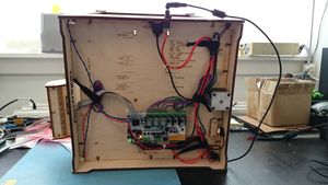
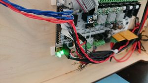
- Mount the board like on the picture using 4 pcs nylon adhesive PCB spacers
- The stripped motor wiring can be mounted directly into the RUMBA screw terminals (it is best to use ferrules on the bare wire). Alternatively mount some DuPont 2.54mm plugs, Molex KK 2.54mm plugs or similar plugs (4-pin) and plug them onto the on-board pinheaders.
- The stripped endstop wiring needs to be mounted using DuPont 2.54mm plugs, Molex KK 2.54mm plugs or similar plugs (2-pin)
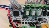
- All the microstepping switches needs to be set at 16 x microstepping (on-on-on), except for the Z-axis which needs to be set at 8 x microstepping (on-on-off)
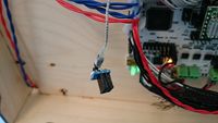
- A USB-B break-out cable can be screw-mounted from the inside of the printer casing, through the hole where the USB cable would usually plug in.
- Using thick wires, mount an external DC barrel jack receptable in one of the holes
- Upload the Marlin for Ultimaker Diamond (RUMBA version) from the Downloads section below
- Make a 12 volt splitter cable or join the wires from the original radial fan that cools the electronics with the wires from the Diamond Hotend cooling fan and mount them using a DuPont 2.54mm plug, Molex KK 2.54mm plug or similar plug (2-pin)
Ulticontroller adaptions for non-Ultimaker electronics
If there is a display controller on your printer:
- Carefully pry open the EXP2 IDC plug using an X-acto knife, an awl or other sharp/pointy instrument (or just cut it off and buy a new 2x5 pin IDC connector)
- Dismount the wire on pin 8 (when counted from the corner with the triangle symbol) from the IDC plug and reassemble the plug.
- Make (solder) an adapter board that can convert 5 volt from the ICSP header into 3,3 volt for the SD-card reader. Then connect the output to the dismounted wire from EXP2 pin 8.
BOM-list for the 3,3 volt adapter board:
- 3x3 size or larger single sided 1-hole island PCB
- 2x3 Dupont female PCB header for connecting with the ICSP header
- 3,3 volt low dropout IC voltage regulator (AP7313, LT1086-3.3 or similar in functionality)
- Short wire to connect GND of the ICSP header to GND of the regulator IC
Downloads
- Diamond head for ultimaker by bencini
- Ultimaker Diamond by RepRap.me
- MK9 wide right.stl by RepRap.me
- Marlin for Ultimaker (preliminary link)
Ultimaker2 Diamond
With some minor differences, the above approach also applies to Ultimaker2
The endstops does not have to be moved, instead an endstop spacer is placed on the rear x-axis bearing (see link below)
The following describes a mod utilizing a pb ExtrudrBoard as described in Adding more extruders together with the existing electronics of the printer.
As the Ultimaker electronics and the Diamond Hotend does not use the same thermistor you have to assign a different thermistor pin in the firmware.
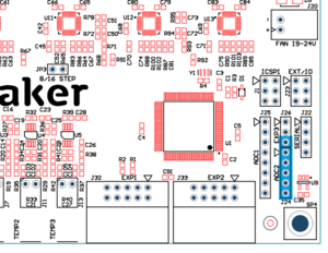 Ultimaker2 board <--> ExtrudrBoard
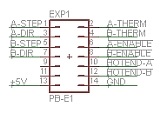
The connections used are shown in blue in the picture above and they go as follows:
| Firmware analog # |
Firmware digital # |
Ultiboard header |
Header pin # |
Ultiboard name |
ExtrudrBoard name |
ExtrudrBoard pin # |
| - | - | EXP3/J26 | 1 | +5V | - | - |
| - | - | EXP3/J26 | 2 | GND | - | - |
| - | D13 | EXP3/J26 | 3 | E2 Direction | A-DIR | 3 |
| - | - | ADC2/J24 | 1 | GND | GND | 14 |
| - | - | ADC2/J24 | 2 | +5V | +5V | 13 |
| A11 | D65 | ADC2/J24 | 3 | E2 Enable | A-ENABLE | 6 |
| A12 | D66 | ADC2/J24 | 4 | E2 Step | A-STEP | 1 |
| A13 | D67 | ADC2/J24 | 5 | Thermistor | A-THERM | 2 |
Firmware changes
Pins.h
#define TEMP_0_PIN 13             // Ultimaker 2 Diamond edit (using ADC13 on EXP4, was 8)
#define TEMP_1_PIN TEMP_0_PIN     // Ultimaker 2 Diamond edit (using TEMP_0_PIN, was 9)
#define HEATER_2_PIN HEATER_1_PIN // Ultimaker 2 Diamond edit (using HEATER_1 as dummy)
#define TEMP_2_PIN TEMP_0_PIN     // Ultimaker 2 Diamond edit (using TEMP_0_PIN)
#define E2_STEP_PIN 66            // Ultimaker 2 Diamond edit (using ADC12 on EXP4)
#define E2_DIR_PIN 13             // Ultimaker 2 Diamond edit (using PB7 on EXP3)
#define E2_ENABLE_PIN 65          // Ultimaker 2 Diamond edit (using ADC11 on EXP4)
Configuration.h
#define EXTRUDERS 3
#define TEMP_SENSOR_0 1
#define TEMP_SENSOR_1 1
#define TEMP_SENSOR_2 1
#define X_MIN_POS 15
#define Y_MAX_POS 189
#define DEFAULT_AXIS_STEPS_PER_UNIT {80.0,80.0,200,96} // (96 or according to your extruder mechanisms)
Setup
- Upload the modified firmware to the printer, turn it on, go to menu Maintenance -> Advanced and choose "Factory reset" in order to make sure no old settings will influence the new setup.
- Follow the on-screen wizard through the setup procedure but when you reach the filament loading don't insert the filament because this procedure is not configured in firmware (and if performed with filament inserted it will probably cause a great deal of clogging in your hotend). Instead just press continue until you reach the filament type selection, finish that and choose Cancel to avoid printing from SD card.
- Go to menu Maintenance -> Advanced -> Motion, choose "Current E" and adjust the value to 1200mA (anything above this value might make your extruder motors too hot for the printed mounts)
- For each extruder press the lever while inserting the filament, then push it through the bowden tube until it reaches the hotend.
Do not try to extrude the filament until all three filaments have been loaded.
- Go to menu Maintenance -> Advanced and use the menu items "Move material (1, 2 and 3)" to move the filament by turning the wheel.
Links
- Diamond Ultimaker2 Diamond parts
- Ultimaker2 on GitHub
- Ultimaker2 firmware (needs some additional menu fixes in order to support the Diamond Hotend)
