SharebotLC/en
Release status: working
| Description | ShareBot LC
|
| License | |
| Author | |
| Contributors | |
| Based-on | |
| Categories | RepStrap
|
| CAD Models | |
| External Link |
ShareBot LC
Per la versione Italiana
http://reprap.org/wiki/SharebotLC
This is the assembly wiki of the ShareBot K 3D printer, I chose to publish a wiki for editing and implementation by all. If you want to hack your ShareBot to change to new requirements or improve it, the cutting and prints files are available at the following link:
http://www.thingiverse.com/thing:28113
Contents
Open the box check that all is arrived in good condition,
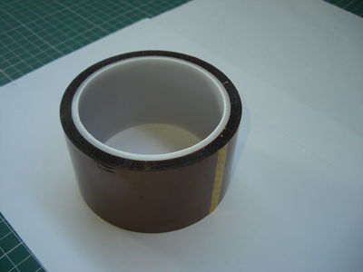
This is what you'll find inside the kit: Kapton tape, an adhesive tape that is resistant to high temperatures, you can use it in the assembly to connect and isolate parts and cables to the extruder or to the heated surface, to isolate the contacts like insulating tape and after as sacrificial to protect the printing plane ;
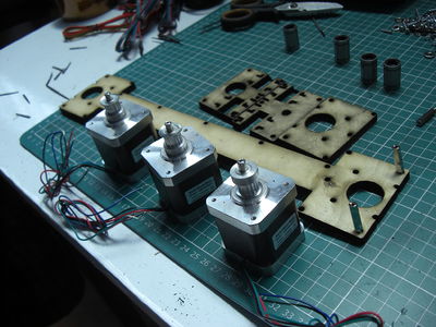
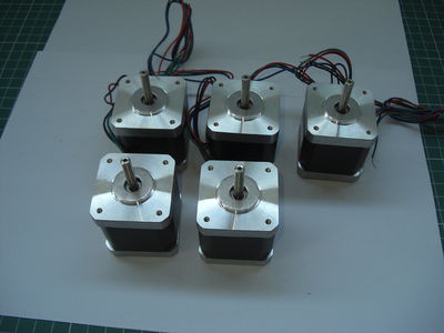
The stepper motors NEMA 17, are 1 to the extruder; 1 for the X axis; 1 for the Z axis (already has the connector and the head wrapped in rubber tape); 2 for the Y axis;
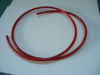
1mt of tire tube D 6mm that will be cut to be used with various purposes;
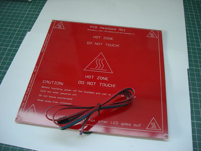
The card / resistance for use as a printing plate heated with welded cable + connector;
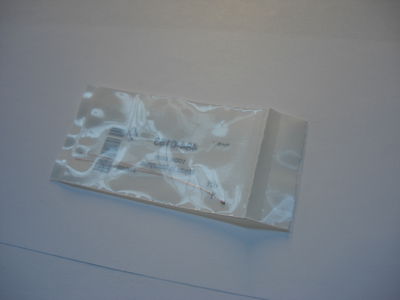
1 thermistor 100K, is used to read the temperature of the platen;
The cable connector;
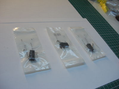
3 electromechanical limit switch,
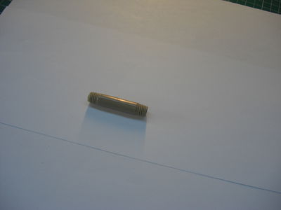
The PEEK tube which serves to hold up mechanically and thermally insulate the heating extruder;
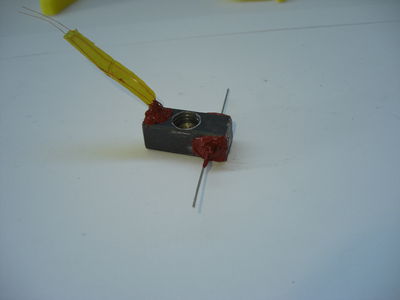
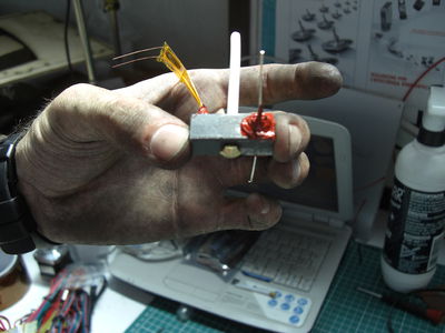
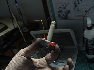
The extruder body already assembled and isolated, the protruding ends of the resistor and thermistor;
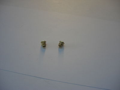
2 brass nozzles, one of 0.48 mm and the other of 0.24 mm, oyu could recognize it by the hole ;)
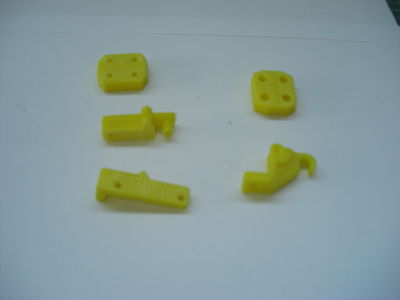
The Z coupling and part of the mechanism of the extruder to push the wire plastic;
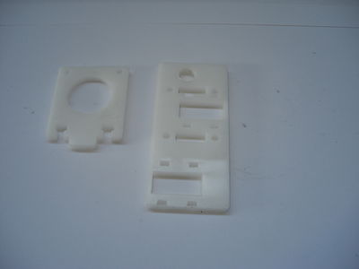
The parts that make up the Plexiglas 5mm carrier of X, start to say it here, they are very delicate, when avviterete interlocking screws be careful;
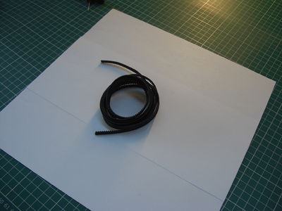
2m synchronous belt 2.5 T which is used for the movement of the axes X and Y;
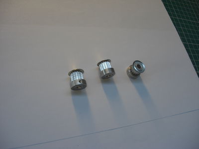
3 pulleys 2.5 T to 16 teeth;
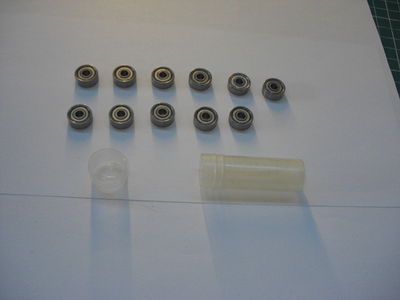
11 bearings 624ZZ;
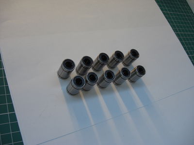
10 LMU8;
1 connector, for electrical connections;
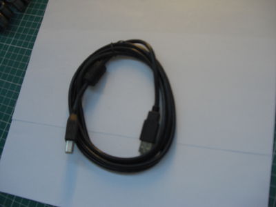
USB cable;
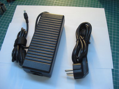
power pack 12V 7A;
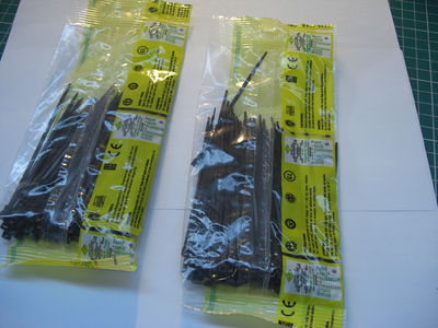
200 cable ties 2,5x100mm;
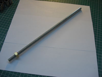
Z screw with the sliding nuts;
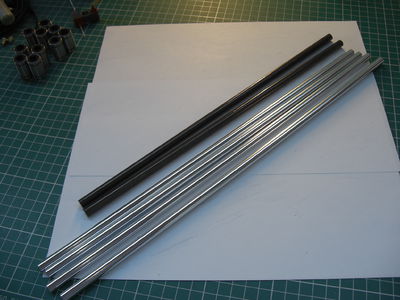
the kit round guides D8mm, 2 to 320mm for the X-axis, 2 to 372 for the Y axis and 2 from 383 for the Z axis;
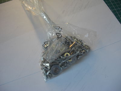
screw kit;
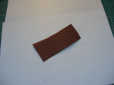
sandpaper;
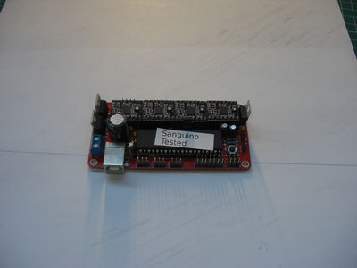
The brain of the printer, including 4 driver (Pololu "green" or Stepstick "blacks");
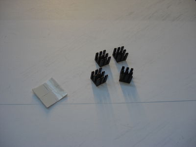
4 heathsinks;
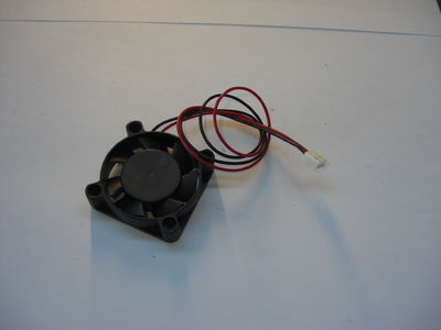
electronic fan;
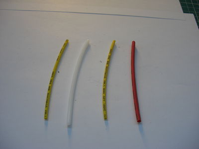
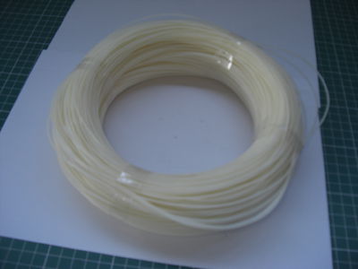
Shrink various sizes and 100mm of Teflon tube D 4mm external
½ kg PLA or ABS;
playwood lasercut kit:
the bridge;
left plate;
right plate;
back;
top + Z axis;
bottom + others Z axis parts;
front + others Z axis parts + some other pieces;
Cleaning and preparation of the parts
Cleaning and preparation of the parts:
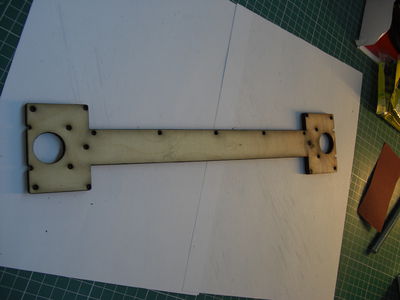
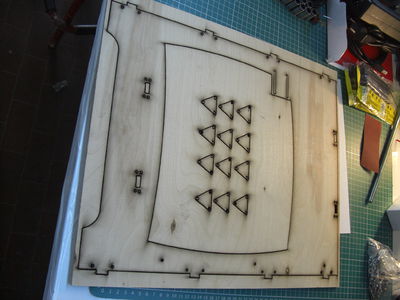
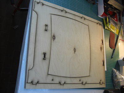
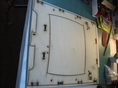
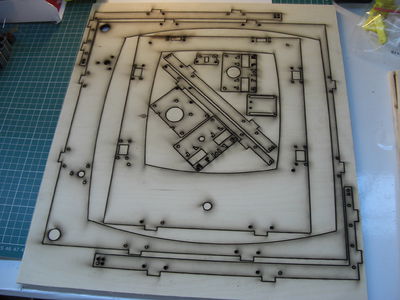
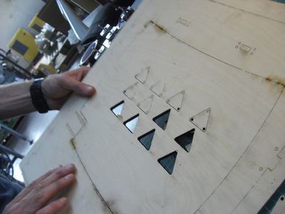
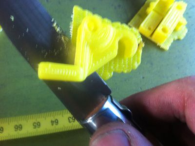
The first thing to do is to separate and clean the parts from scrap wood and black or wood residues left by the laser. The delicacy never hurts, for the separation can help you with a knife while cleaning with sandpaper. The shell can be left natural or painted as desired.
Even the printed plastic parts that make up the joint Z and part of the extruder and the parties plexi may need a cleaning.
Once this is done we proceed with the assembly:
Body
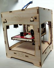
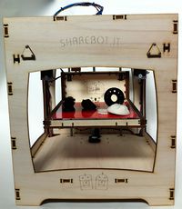
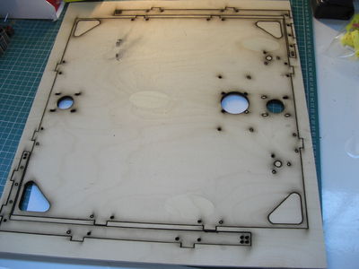
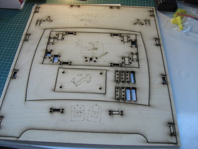
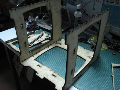
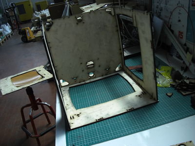
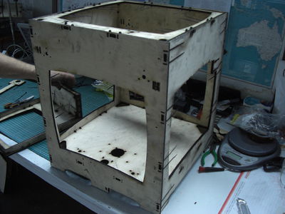
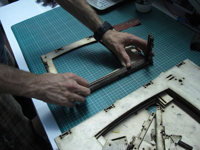
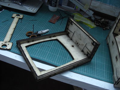
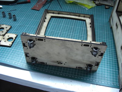
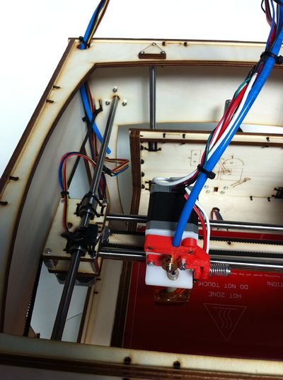
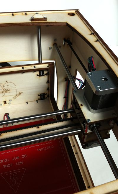
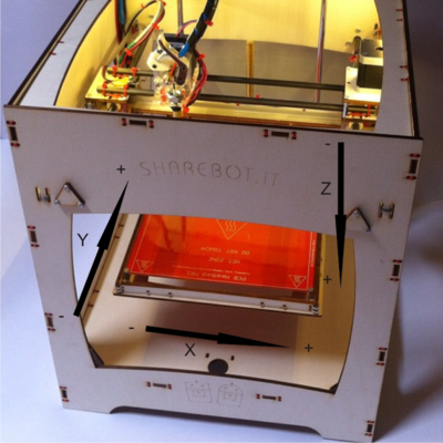
THE BODY: First, take the wood parts that will form the body of the machine, which is nothing more than a wooden box consisting of two caps above and below (the cap top is open while the bottom is closed), and 4 sides. We support the rear of the machine on the table in the orientation shown in the picture, with the slots lower left (has 4 slots near the holes of the rails, two high and two low) and those high on the right. We can get us into the side panel of the SX (the one with the 2 slots, which must be kept upwards, will be the location of the end stop Y), and that of the side DX (has additional holes to lock the cables going oriented towards the rear.
Now we can proceed with the assembly of the cap down, wedging them as in the picture, the two large circular holes are oriented close to the rear. Pay close attention to the orientation of the two panels top and bottom holes for the Z guides and motor are not central, but offset from the center towards the right machine, then make sure to properly set the two panels.
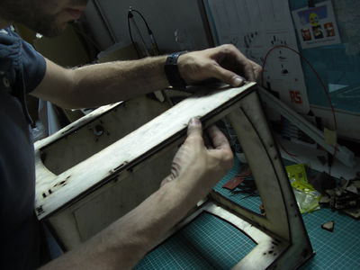
Finally, you can proceed with the interlocking of the top cap (retaining the thin portion towards the front and the thicker towards the rear) and the front panel.
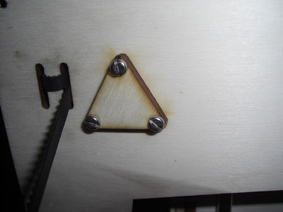
Now to complete the assembly of the body we have to go fix all clamps locking the joints and cut off the excess. You also have to fix with 12 M3x16 screws and 12 nuts, 2 block triangular guide on the rear panel and 2 on the back panel.
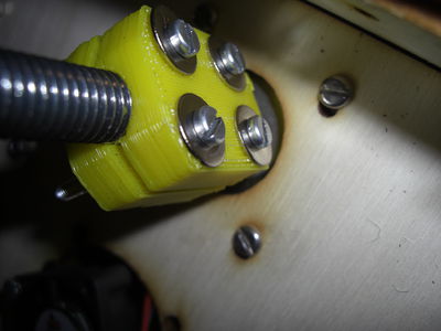
We can still proceed with securing the stepper motor of Z (the one with the wired connector) into the hole, with 4 screws M3x8, should not be tight as when you are finished and turned on the printer you will need to align motor / screw / nut scroll , and finally to lock the motor in the desired position. The worm and the joint are to be assembled at a later time.
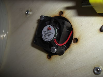
To the second hole on the bottom always fix the cooling fan of the card, mounted from above that blows upwards. The fan mounting is done with 2 screws M3x30 2 M3 nuts and 4 washers, screws pass into the large hole in the wood, leaving a washer on each side of the plate, tightening the nut will close the clamp on the wood washers fixing the fan.
X Y Bridge
Bridge X / Y:
This is the operation that requires more mental energy, focus and then make sure not to be disturbed ...
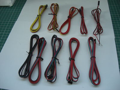
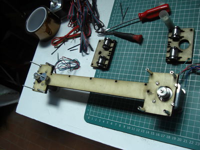
The pieces that make up the bridge of your ShareBot are: Bridge and wooden plates, 3 stepper, 3 pulley, 8 spacer 20mm, 10 624zz 1 o 2 washer 5x20 6 LMU8 2 smooth rod 320 mm 2 smooth rod 372 mm 1 microswitch 1 x 1 m 3-wire cable (yellow, red, black) 3-wire 4-wire x1 mt (black, green, red, blue) 5 screws M3x40 4 screws M3x16 12 screws M3x8 27 M3 nuts a lot of cableties
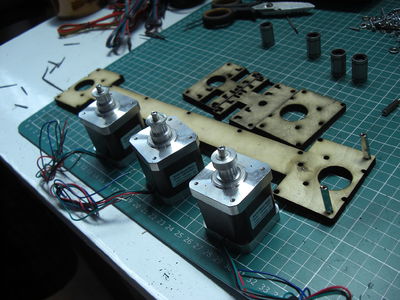
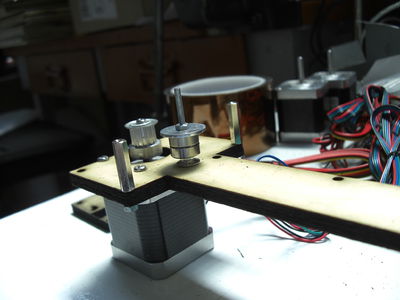
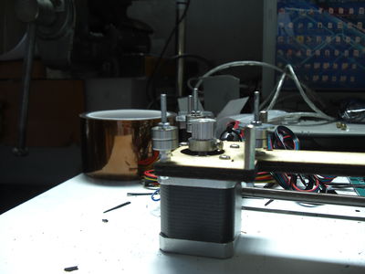
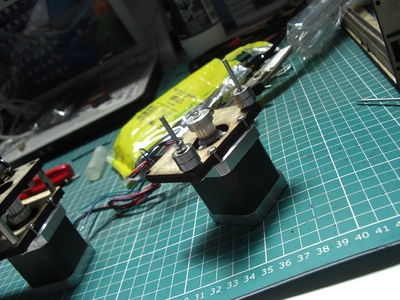
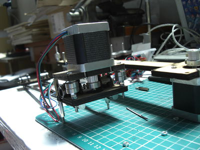
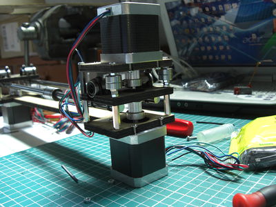
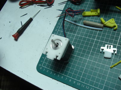
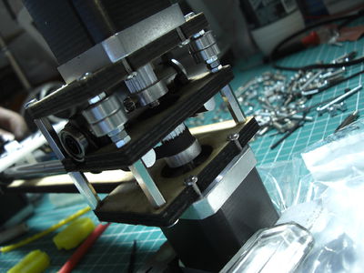
begin assembly, first assemble the 3 pulleys on board of the 3 stepper motors, and shake the grain (small Allen screw that is screwed into the pulley to lock the motor shaft), as shown in photo (2 pulleys with the grain towards the engine and 1 pulley with the grain upwards), at a later time we will adjust its height exact aligning the pulleys with belts.
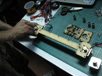
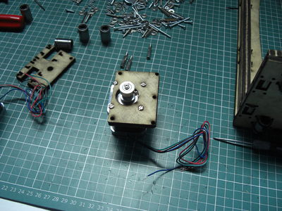
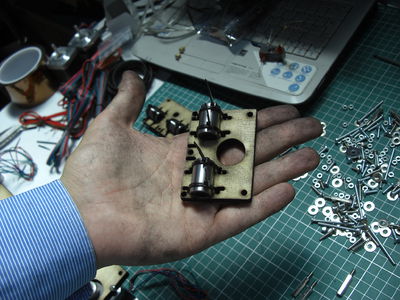
We mount the motors on the bridge and on the plate (the plate that goes with the pulley on the contrary), using screws M3x8.
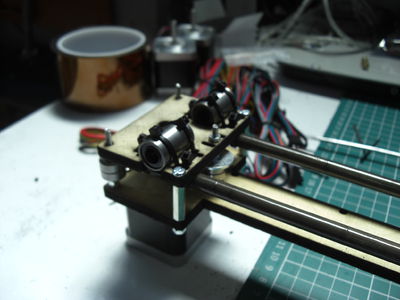
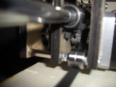
Now looking at the bridge from the front (small holes on the side of the bridge remain behind), we begin to mount on the SX two spacers as in the picture and the screw M3x40 resend belt that serves as the X axis, with two bearings and two washers and two nuts, in this order: nut / washer / bearing / bearing / washer / nut.
As picture complement fixing to the outer sides left another 2 screws M3x40 blocked with 2 M3 nuts on the right side and 4 spacers blocked with 4 M4 nuts.
The two screws M3x40 screw on the left side must be as follows: 3 nuts M3 / 2 bearings / 1 M3 nut.
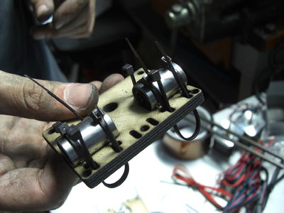
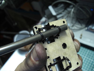
With 8 cableties going to fix 4 sleeves to the two plates, keeping the lines as in the images.
Now prepare them as in the photo other 4 cableties for each plate, which will serve for the clamping of the guides X.
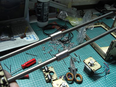
Insert the guide and lock the cableties on the first side.
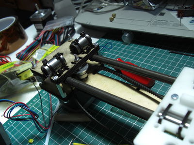
Insert the two sleeves slide X-axis and proceed with the mounting plate also to the other guides. (For orientation, we sleeves and going up, the plate with the large hole in the center of the right and the one with the small hole on the left)
Take the single plate with mounted on the engine (the one with the pulley inverted) and on the side where the engine protrudes screw on as the first 2 screws M3x40mm and nut M3 sequence 1/2 ball / 3 M3 nuts
The two holes in the side of the plate mounted two spacers blocking with 2 screws M3x12, then affix the plate to the right plate (the one with the big hole) and tighten it by screwing 4 spacers as in the picture
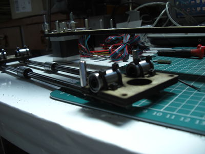
Now we can combine the three plates with the rails of the bridge, as in the picture, RIGHT blocking all with 4 M3 nuts from below,
left blocking from above, with two screws 3x12 for the spacers, 2 nuts M3 for the screws M3x40, and a nut M3 to lock the screw M3x40 the postponement of the belt X.
At this point we can proceed with the alignment of the pulleys to the bearings and attachment of the grains,
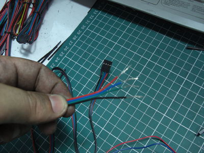
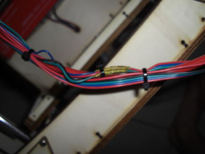
Then we go to the union of 4-wire engine with 4-wire extension cords, clean the wires head, insert a piece of shrink for each wire and joint keeping the colors,
It is not necessary to solder (if you welded does not hurt), just wrap the two ends of each other, cover with heat shrink and heat shrink it to withdraw and isolate the contacts. If there are problems with the shrink can fix and insulate the joints with a piece of tape Kepton.
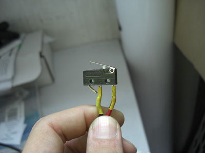
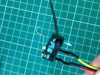
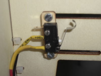
Wired the three extensions on the three motors connect the 3-wire cable with the micro, clean the red and yellow, the black wire you can cut it shorter and isolate it (you do not need this kind of switch), connect either the red and yellow to the C and NO micro pins, then we stop and isolate with a piece of heat shrink or kepton.
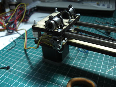
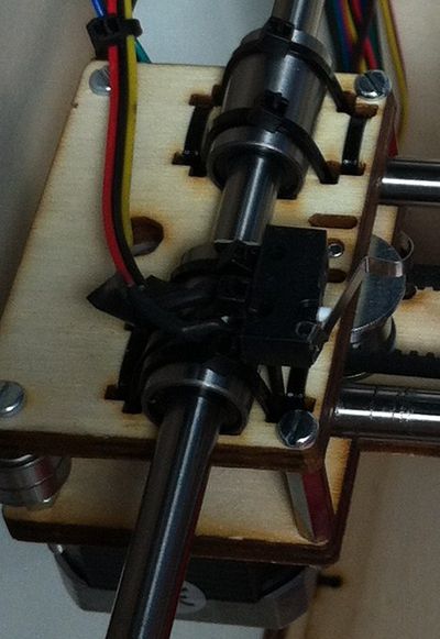
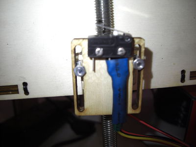
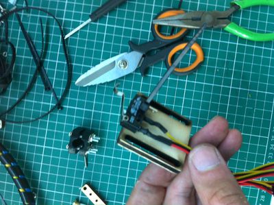
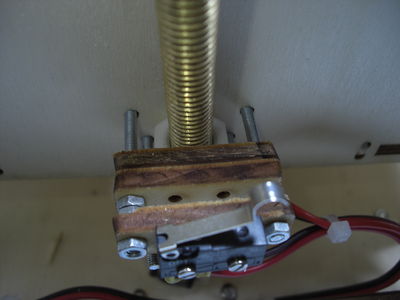
Let us fix Micro X-axis with a clamp to the spacer as in the picture, the top edge of the micro will be flush with the plate high, after verify the height so that it snaps into contact with the carriage of X. Be sure to put the band in a location that does not prevent the "click" to the micro.
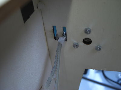
Another possibility (feels better) securing the Micro X-axis is performed in the photo below, by passing a cable tie through the holes of the sleeve bearings also takes a hole switches and locks!
Now let's staging of the extruder and the carrier of X.
X axis and extruder system
Take the last stepper motor, and put it on the plexy 5mm as in the picture, the motor cables let them upwards,
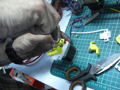
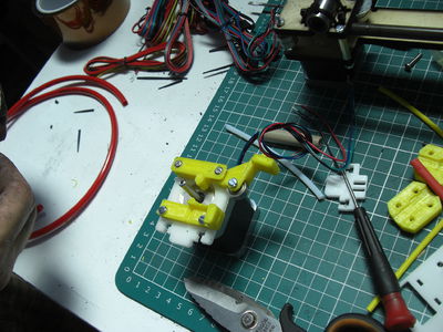
Then take the printed extruder as in the picture and put it is against the two holes top of the engine, you need to cut a piece of hose and you have to insert it support. Now we can tighten two screws M3x16.
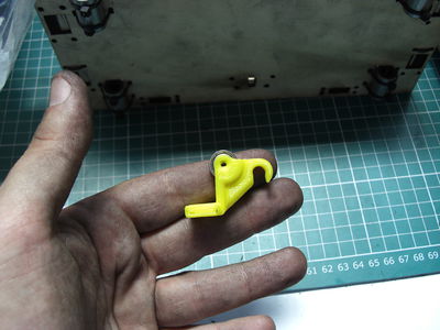
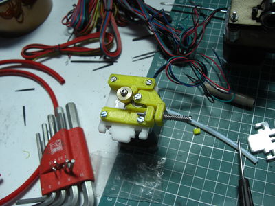
Now we take the locking lever of the filament, clean up the seat to allow the entry and sliding bearing 624zz, block with a screw M3x12, screwing it directly into the plastic, serves not tighten up at the bottom.
Now we block with two screws M3x12 also the lower part of the extruder and lock the support of the bearing tube to the air as in the picture.
At this point we take the pawl brass (is a small brass bushing toothed) and shutters with the grain of the spindle motor. We also add a screw M3x40 with spring and washer (the washer goes on the plastic to keep it from digging king by the spring) and the hole's put on the bottom piece should be placed in the home a M3 nut, tighten the screw.
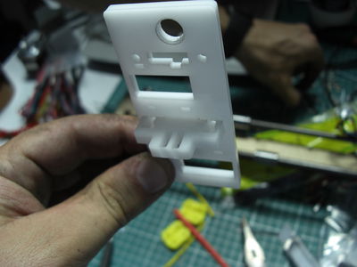
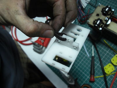
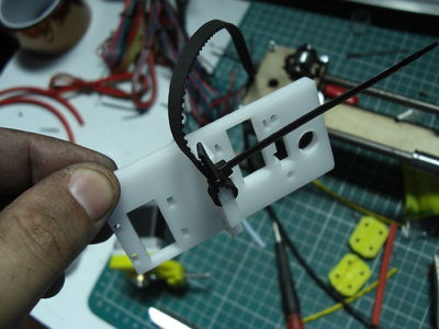
Take the plexy plate in the picture, and lock on the door strap, locking with 2 M3x16 and 2 nuts M3, MAKE SURE it is delicate, if you pull too jump wings, point screws and nuts, tighten and fasten with minimum of glue.
Now cut a piece of belt 700mm lock and a head with a cableties on the tensioner (there are about 2m belt, so it is very generous to allow the tension first, then cut off the excess).
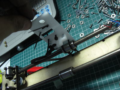
Now develop the clamps locking sleeves and fix the sleeves of X on the rails of the bridge.
Now we turn the belt around the pulley and resend, and go to tension and secure it with another band on the other slot of the carriage. We can see already time to give proper tension to the belt, lock and cut off the excess in the future if we require further tension not want to disassemble the straps can print and mount a supplementary tensioner as follows: http://www.thingiverse.com/thing:16449 http://www.thingiverse.com/thing:10082
Now we can mount the extruder on its slot, and secure it with two screws M3x12 and two M3 nuts.
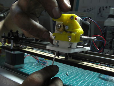
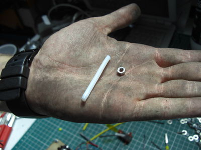
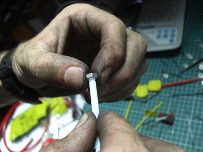
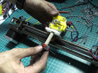
For mounting the HotEnd we start by taking the Teflon 100mm tube and cutting it exactly in 2 equal parts, now lets take we the M4 nut that is in the kit only to this purpose, and screw on one side of the teflon stick of about 10mm, will see that when the unscrew have imprinted the thread on one side of the stick of teflon, (repeat the same operation with the other).
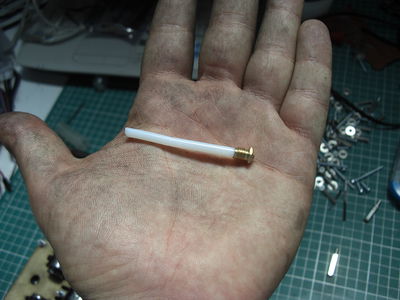
Now we proceed by screwing the teflon tube inside the nozzle,
Now screw on the nozzle with the stick in the extruder body, (to set the printer and learn how to use games with the nozzle of 0.48 mm)
Screw on the hot body the PEEK tube
Now screw on the HotEnd complete on cart X
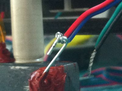
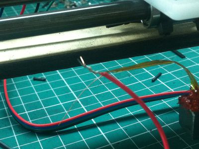
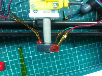
Proceed with wiring of the HotEnd, add 50m of white cable to make longhest the thermistor and resistance cable (some kit could have 2mt 4wire / 2wire cable for thi purpose), we fix the leaders of the thermistor and the resistance to the white cable, and after this in the 4-wire cable and 2-wire cable, (for resistance can be created with tweezers two rings for fix the thread) For resistance using the 4-wire cable, mate in 2 and 2 to connect to the resistance. For the thermistor using the 2-wire cable.
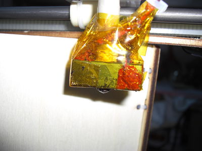
isolate with tape KEPTON, do not use other tapes or shrink as melt.
If you want you can play with the kepton the heating body to isolate it better and avoid accidental burns.
Z plane
For the assembly of the Z plane are:
The wooden parts, which are: 4 shoulders, Z plane, guide plate, Z, two reinforcement plates, plate nut, 2 microswitch plates, 6 screws M3x40 2 screws M3x30 12 M3 nuts 2 screws (M2 replaced by cabletie from 20/08/2012) 2 nuts M2 (from 20.08.2012 replaced by cabletie) 1 microswitch 1 cable 3-wire + connector 4 springs 1st floor heated PCB (http://reprap.org/wiki/PCB_Heatbed) 1 thermistor 1 2-wire cable (red / black) + connector 4 sleeves 1 nut M10 cable ties
Couple the two and Click them back on the seat of the Z plane, block with the cableties in the holes, taking care to leave the head of the cabletie in the inner corner of the junction. Do the same on the opposite side, then fit the structure obtained in the plate sleeves, leaving the drawing inward and secure with cableties.
Also fit the two reinforcement plates at the top and bottom ring as pictured above, and secure everything with the cableties.
Now we put the sleeves in the appropriate joints and lock with the clamps.
Now we turn to the assembly of the nut and slide the switch Z. Giuntiamo the limit with the 3-wire cable, as before, we need to connect the red and yellow to the micro either the C and NO, isolate the black.
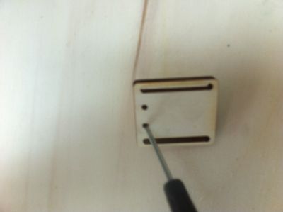
Then prepare the anchor plate of the end of stroke, with a screwdriver to dig a seat of a few mm inside the end of the race plate, support the two nuts and M2 with a cableties or a cableties block them, so that they are flush. Screw on the detector with 2 screws M2.
20/08/2012 by the fixing of the proximity switch is via cableties as in the image below, both for fastening onto the small plate of Z that for the fixing of the proximity switch on the next plate Y!
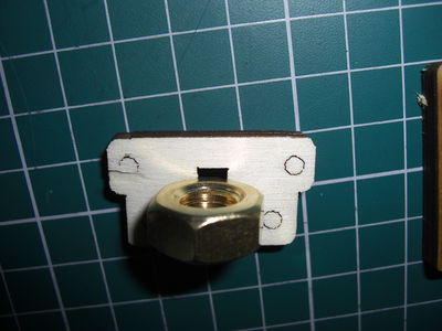
Now slip the 2 screws M3x40 and 2 M3x30 into the holes of the plate Z door sleeves, making them protrude outwards, we place the M10 nut in the slot and insert the lock plate, fix with 4 screws, then the screws M3x40 screw on other 2 M3 nuts, insert the plate and door microswitch and lock with two M3 nuts.
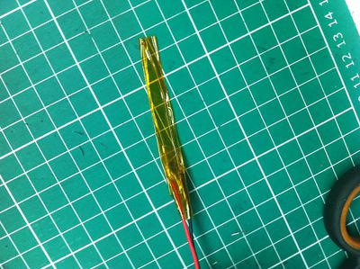
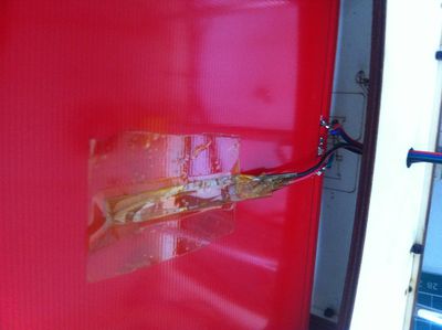
Take the thermistor 100K, and with tape kepton isolate the two copper contacts so they do not touch each other (type thermistor hotend), then move the thermistor joint contacts with the 2-wire cable and isolate with tape kepton. Now more with tape kepton we can attack the thermistor at the center of the PCB heated.
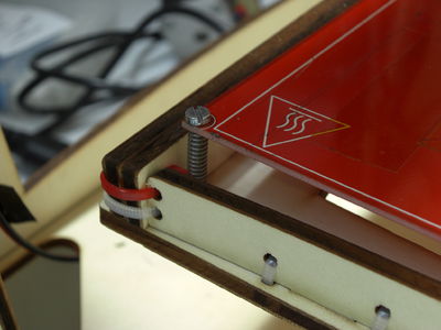
Now we take the PCB and we pass the 4 M3x40 screws into the holes, insert 4 springs on the stem of the vine and we pass the screws even within the four holes in the wooden floor, at this point we stop with 4 M3 nuts.
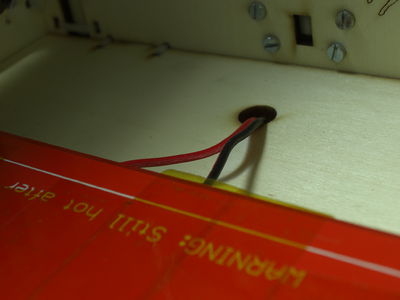
The thermistor cable and PCB can pass through the hole as in the picture.
Assembly printer
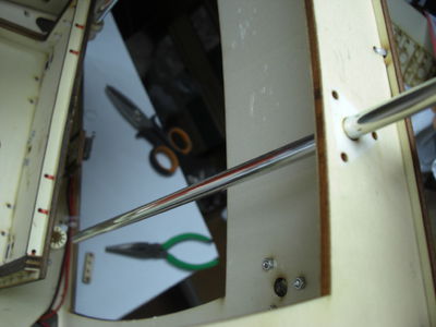
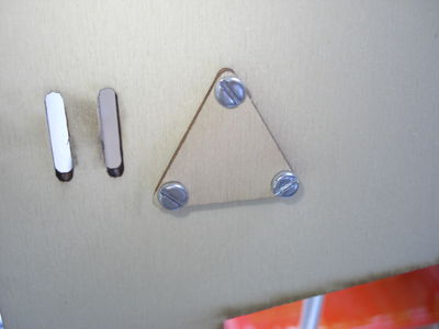
Now take the body pre assembled and the Z axis, insert the Z axis within the body from above and insert the two guides Z, passing them to the sleeves, the axis Z. we block the guides with the triangular plates and lock with M3x16 screws + nuts M3. If the guides should have game within the premises of the body, turn the tape over the heads of the rails until increase and lock into place.
Now we can insert the endless vire from inserting and screwing in the nut down, insert the joint between the the Z screw and the shaft of the motor (the shaft is wrapped in rubber tape, is used to give the correct grip between post and come and help dampen vibration and alignment, if the tape was too you can unroll taking it to bring the post to the right thickness for insertion into the joint). Here advice to tighten the screws to a minimum of the joint and the motor Z, once turned on the machine will move forward and behind the axis Z for allign the system, at this stage will block screws of the motor and coupling.
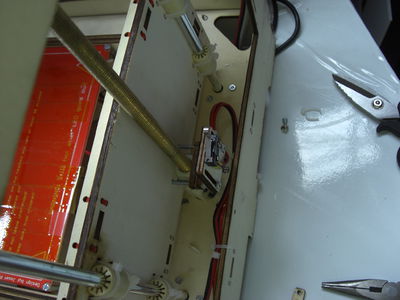
Now let the installation of the bridge, in the same way we insert the two guides Y in the bodywork by passing inside of the sleeves of the sliding bridge XY, lock guides with plates triangulated screwing 6 screws M3x16 with 6 nuts M3.
Now we need to lock and tighten the belts of the two motors Y, we take one end of the first belt and put it into the slot adjacent, then fix it with cableties, causing the two sides of the toothed belt are paired. On the other hand tension the belt without exaggeration, let's go over the slot and filter with a clamp. The excess belt can be cut.
It should not be hard, just that once blocked to move forward and behind the engine (must be live) did not play. Even for these belts after tensions can be performed by downloading and printing of the tensioner.
----------------------------------
Electronics and wiring
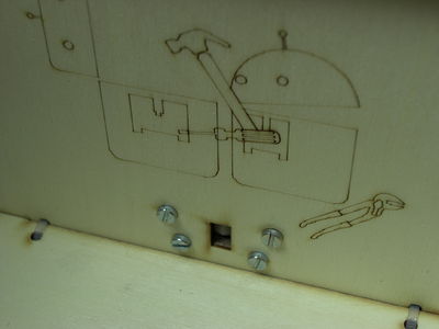
Wired as seen previously for the Z axis also the microswitch for Y axis (if kit shipped after 20/08/2012 lock the micro with the cableties), fix the wooden plate with two screws and two nuts M2 M2, taking care to collect the nuts M2 in the same way as the plate limit Z. With 2 M3x16 screws and two nuts M3 block the plate carrying the limit on the slots as in pictures.
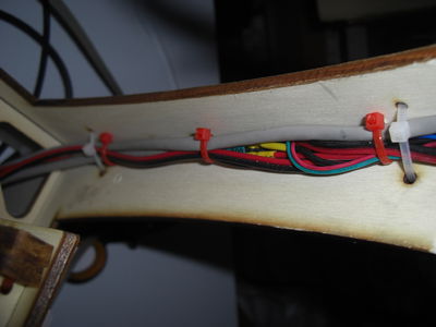
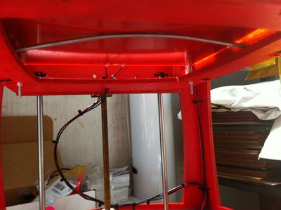
Now we order all the various cables by placing them in the appropriate way and secure them with cable ties or tape kepton rectangles, bringing them up to below the base plane of the printer.
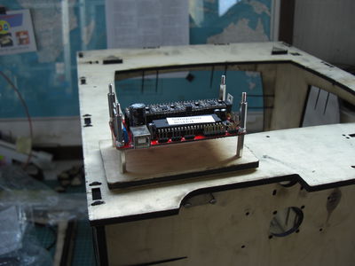
The electronic board is already tested and prepared with loaded onto the bootloader and firmware Marlin modified for use on the 3D printer ShareBot. Prepare the electronic card (http://reprap.org/wiki/Sanguinololu), we take the protection plate, screwon over 4 spacers and lock with 4 nuts M3, then support above the electronic board and lock with 2 M3 nuts for each spacer now screw on over 4 spacers. Take sinks, we apply above a square of double-sided attack on the chip and driver of the 4 engines, make sure that the heatsink is not touching any contact card, and vacate the small screw to adjust the output voltage to the stepper motors, will help us reach after the first test, if necessary we should adjust the power to the individual motors (http://reprap.org/wiki/StepStick or http://reprap.org/wiki/Pololu_stepper_driver_board).
The underlying Vref of the individual axes are already set! Are reference values for individual machines may vary. For readout mode Vref refer you to the pages of individual drivers.
For drivers Stepstick the value of Vref I've found are: X 1.12 Y 1.2 Z 0.9 E 1.2 Pololu driver for the value of Vref I've found are: X 0.3 Y 0.3 Z 0.25 And 0.3
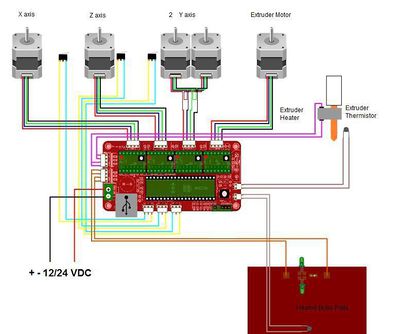
Now connect the cables to the connectors of the various following the wiring diagram below, in the firmware loaded has been inverted output of the motors Y Z with that of the engine so as to capture the output in parallel provided on the card for engines Z engine Y. When a motor rotates in the opposite direction to the direction wanted, just unplug the connector (card not supplied) and reconnect the motor reversed by 180 °, the motor will rotate in the opposite direction.
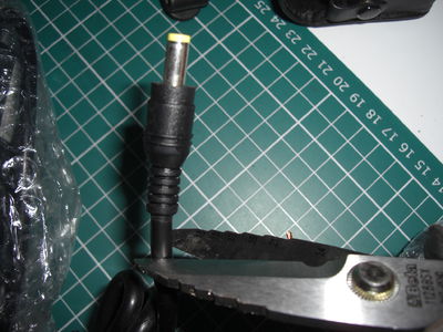
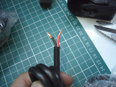
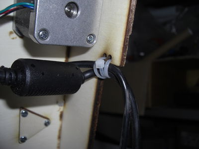
Preparing the Power Supply: Take the power supply, cut the plug end and clean the head of the wires RED and BLACK + -, link to them hours to the two contacts of the connectors and filter out the screws. In their + and - contacts of the connectors to connect the red and black wires (always respecting the polarity) of the cooling fan, take two pieces of white wire and strip, connect one end of both wires together with the fan in the connectors, connect being very careful to follow the + and -, the wires to power the electronic card. Now we support block the electronic board at the base of the machine and fix with 4 M3 nuts. We arrange the wiring with cable ties, and filter out the power cord and USB cable ties always with the appropriate holes as in the picture.
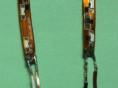
If you want to install the LED, soldering the red wire to + of the LED strip and the black wire to - at this point we can remove the protective film from the led strip and stick them inside the printer, then bring the wires which will connect directly to the connector red with the positive and the negative in black with the connector.
--------------------------------------
Software
Management software for DIY 3D printers there are several, for practicality and reliability we have chosen PrintRun, downloaded at the following link:
http://reprap.org/wiki/Printrun
or you can download the Windows version ready for the printer and is already configured with Slic3r
https://dl.dropbox.com/u/51473469/printrun-win-slic3r-SB.rar
Slic3r is the software that converts the *. Stl in *. G-Code, which is the language made up of coordinates that reads our car. You can download Slic3r the following link:
https://dl.dropbox.com/u/51473469/config% 20slic3r% 20sharebot/config024.ini
https://dl.dropbox.com/u/51473469/config% 20slic3r% 20sharebot/config048.ini
at this link you can download the file printing parameters dedicated to the 3D printer, there is a parameter file to print using a nozzle 0.48 mm and 0.24 mm for the one to be, you have to copy the *. ini in slic3r folder from printrun to make sure you load your settings open "slicing settings" then "load config" in order to select the correct parameters. Although optimized parameters for this model 3D printer may require some minor changes to the printing parameters that may vary from printer to printer, also some parameters such as the temperature of extrusion may vary depending on the material used (ABS - PLA), color and provider, then may be necessary minor modifications.
As an alternative to Slic3r that we found especially useful for the automatic creation of media and the raft is SkeinPyPy be downloaded at the following link:
Once downloaded and installed you can "transfer" the print settings of your printer that you use on Slic3r in Care.
PRINTRUN: (Http://reprap.org/wiki/Printrun)
Printrun is one of the most widespread and used for controlling a 3D printers type RepRap, has been realized by Kliment, is part of the "package printrun, which also includes printcore and pronsole.
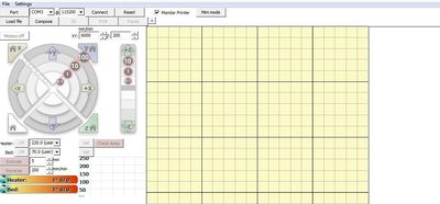
The program consists of 5 blocks, which are: the user panel, the joystick to control the axes X, Y, Z the control panel extruder and the platen, the platen the console
The user panel the user panel is placed in the upper part of the program and is as follows:
It consists of 15 buttons that perform the following functions: File: you can open a file, edit it, clean the console, navigate to the projector, exit the program;
Settings: creation of new buttons, program settings, program generation G-Code;
Port: there is a button itself, consists of two boxes:
The first indicates the port to which you wish to connect to connect to the printer, open the drop-down menu you can see those available; The second indicates the data transmission speed with the electronic board, in our case are 115 200 Baud rate;
Connect: This button, when pressed allows you to connect to the printer and activates all functions; Reset: This button allows you to reset the printer; Monitor Printer: if checked enables the automatic reading of the temperature of the extruder and the platen; Mini Mode: This button zooms the program window showing only the part of the user panel and console; Load File: This button allows you to open a file *. Stl, *. OBJ, *. Gcode. If the file is an STL or OBJ will initiate a conversion in G-Code; Compose: from here you can access a window to format multiple files on the floor of the press; SD: This button allows you to load a gcode directly from the memory card on the board (not all electronics have this option); Print :: With a G-Code loaded let you start the print cycle; Pause: to pause printing, enable the Resume button and Restart; +: Allows you to add a custom button;
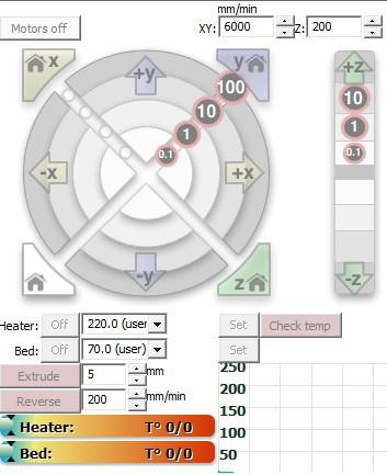
The Joystick
Motor OFF: Allows you to switch power to the stepper motors; Mm / min: here are set the speed of JOG (jog) of the axes X, Y and Z; Joystick XY: This panel allows you to control the movement of the axes in JOG (manually) and the related cycles HOMING (the axis goes to read the detector to know its exact location), the movements are controlled by buttons on the pad, over the direction (+ and -) movements can be of different sizes (mm): +100 +10 +1 +0.1 -0.1 -1 -10 -100
- Joystick Z: next to the XY pad is the pad for the Z axis, you can move the Z axis in the positive (you move the plan from the extruder) and negative (approaching the plan extruder) in various measures:
+10 +1 +0.1 -0.1 -1 -10 Panel Extruder: The extruder panel allows you to adjust and view the temperature of the extruder and the platen. Control the motor of the 'extruder positive and negative. Heater: OFF: Stop heating the extruder; Temperature ° C: in this box you set the temperature you want to achieve; Set: pressing this button activates the heating extruder according to the desired temperature; B: OFF: stop the heating of the plan; Temperature ° C: in this box you set the temperature you want to achieve; Set: pressing this button activates the heating of the plan according to the desired temperature; Check Temp: pressing this button, the console will read the current temperature; Extrude: This button allows you to start the engine of the extruder, according to the settings given in the boxes at the right: mm: mm identifies the filament that are pushed; mm / min: identifies the speed of estusione; Reverse: This button starts the engine dell'estusore but with opposite movement, according to the settings given in the boxes at the right: mm: mm filament now indicates that they are portrayed; mm / min: now is the speed of retraction; Temperature indicators: Heater: temperature is shown in degrees centigrade extruder B: temperature is shown in degrees centigrade of the bed The Dish This panel allows you to view the object that will be printed and to follow the movements of the printer via graphical display of the route print in black and route print in red.
The Console The console is the panel on the right is made up of three elements: A window showing the LOG; A box in which you can write code strings G-code and send them directly to the machine; The SEND button to send the codes entered;
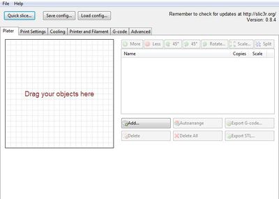
Slic3r
In this window you can paginate and dubblicare files to be converted to g-code, you can also edit files scalandoli or swing them.
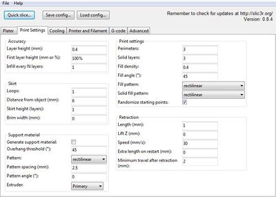
Accurancy: The height of the layer, Layer Height, is a very important parameter and must be compatible with the diameter of the hole extrusion nozzle, For the 0.48 mm nozzle usually sets the value of 0.35mm, it is advisable to avoid values greater than 0.4 mm, even using lower values will have higher quality on the walls.
Skirt This parameter allows you to make a line around the perimeter of the printed object, The Skirt allows you to extrude and clean the nozzle before the actual release of the object and allowing you to see if the extruder is set at a height right to the plane.
Print settings Perimeter, the value set to 2 means that will be printed 2 shells solids to form the surface of the object. Solid layers, is the number of full layers that are made on each surface that extends horizontally. Fill density, is the percentage of filler that is used in the printing of the object, with 0 will print only the empty shells of the object, with 1 will be totally full, usually sect around 0.4. Fill angle indicates the angle at which it will be made the object's fill. Solid fill pattern and fill pattern, identify the geometry of the fill.
Retraction: is the shrinkage in mm which carries the extruder to each shift in G0 (passage between a point where print G1/G2/G3 to another point of printing, to avoid leaving a strand of molten plastic or a drop). Length, identifies mm of plastic wire which will be retracted during the movements, may depend dall'estursore used or the type of plastic used for printing. Lift, identifies the lifting axis z are executed when the rapid moves G0 so as not cocciare against parts already printed with the nozzle. Speed, identifies the speed with which the wire will be portrait. Extra length on restart, indicates mm extruded over when you resume printing after a shift that has been applied to the retraction. Minimum travel after retraction, this value is used to prevent retraction if the point where you are about to print is next.
Support material: represents the options for automatic positioning and printing of substrates for printed objects.
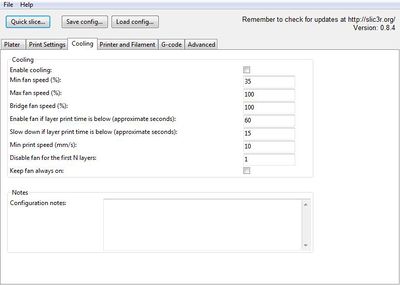
Cooling setting, are a set of parameters to manage the cooling fans of the hot end, where the printers are provided.
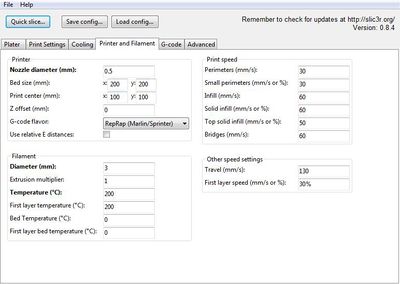
Here we have the machine settings, the filament used and the temperature of the press.
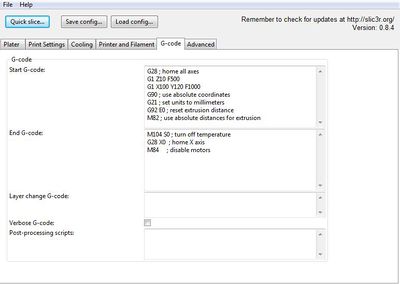
In this window there are the header and the end of the G-Code, set for the printer.
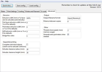
Here are the expert parameters useful can be the first parameter: extrusion width, is the filling of horizontal planes, if you print a whistle and leaking air from the sides or a vase / glass and loses H20 from the bottom then you have to play on this parameter.
First printing and calibration
Let's current: You have just completed the assembly and wiring of your new 3D printer, now is the time to give current and calibrate the hardware to accomplish your objects.
Check again that the power adapter is properly connected to the positive pole and negative card. Turn on the printer and connect the USB cable to the PC, expect it installs correctly the card driver. If your PC does not install drivers automatically dell'FTDI (serial / USB on board) you can download them at the following link:
http://www.ftdichip.com/Drivers/VCP.htm
launch Printrun, we set the correct COM, we set 115200 BitRate and click on CONNECT ... Connected to the card try first the meaning of the engines by clicking on the JOG (Arrows manual movement of axes), move 1mm Z + (the platen is away from the nozzle), Z-(the plane is closer to the nozzle), if it goes on the contrary, NOT turn the printer, scolleghiamo the USB and turn the motor connector Z of 180 °. Then we test the X axis (moves the nozzle SX to DX and vice versa) in X + 1mm nozzle goes to DX 1mm Xl'ugello goes towards left, now it's up to Y, Y + 1mm the two motors must move in the same direction, and the nozzle will move towards the bottom of the printer, Y-1mm and the nozzle is move towards you.
Now activate Monitor Printer and click on Check Temp, if everything is correct we will see or less than the ambient temperature of the extruder marked in the table and the floor of printing. Now to set the temperature of the extruder at 240 ° C and the plan to 60 ° C, see the temperature rising in the chart below. If we see smoke the extruder do not worry, the first heating evaporates the residual lubricant machining of metal parts. After the 180 ° C we can test the extruder, (under 180 ° C the extruder extrudes not for security) we click Extrude and check that the wheel turns clockwise to push the filament nell'hotend, if you click verify that goes in reverse direction opposite. If everything works the way here, we check the end positions by clicking on the button of HOMING individual axes and ensuring that each axis arrives at 0 (the proximity), and worms properly.
Align the Z plane:
with the fixing screws of the motor and those of the coupling Z soft run the Z-axis at the top and low back and forth until the worm of Z does not flow straight, at this point shake the motor screws and Z of the joint.
Attach a protective layer of Kepton on the printing plane.
It may happen that the PCB (http://reprap.org/wiki/PCB_Heatbed) when heated embarks a little, you can avoid in this setting a piastina glass above the surface of the PCB, and print on latter. Otherwise using the print RAFT (grid print below the item) is can compensate for this. To overcome this problem another solution is to take a piece of aluminum or metal, bend it slightly and snap it under the plate, so as to keep it flat, as in the picture.
Now we set the level of Z: Make sure that the hot end and the floor are at room temperature, HOMING we click the Z-axis, click on MOTORS OFF, manually bring the nozzle of the press in the vicinity of an angle, by adjusting the plate door microswitch Z and 4 screws from the heated surface, we are that the PCB is heated after the HOMING in vicinity of the nozzle. Moving to manually repeat the process on other 3 corners of the heated surface.
Now let's try to extrude, slip one end of the wire PLA / ABS in the KIT inside the extruder, and let's scroll to the bottom all'HotEnd, shake the screw clamping the extruder up to load a little the spring, bring manually in the temperature HotEnd (keep ourselves also Altini, then on decreasing up to the temperature optimal, 230/240 ° C then descend until you find the optimum temperature), we set of filament 20mm and 100 mm / min speed extrusion, click on Extrude and verify that the filament comes out of the nozzle, then verify how much load the clamping screw of the filament, the filament look in near the latch brass extruding making a full circle we have see that the filament moves with constancy in the extruder down, otherwise pull yet the screw. Now we are ready to run the first press council to realize the 20mm box, so to verify that everything is working properly, the measures and the teams X and Y printer.
https://dl.dropbox.com/u/51473469/20mmbox.stl
The press does not stick to the bed: Make sure that the bed temperature is set to the right value. Make sure that the bed is clean of any fingerprints or other material. Use alcohol to clean bottom. Make sure the nozzle does not drag on the platen. Make sure that the distance between the plane Z in Home and the nozzle is approximately that of a sheet of paper.
The nozzle drag all the press: Make sure there are no residues of plastic, or around the nozzle that may be been left from a previous print, even a small piece of plastic attached to the side of the nozzle can ruin a print. My car makes a lot of squeaking and rattling noises: Make sure everything is aligned and perpendicular. With the engine off, it should be able to move easily in X and Y manually. Apply a thin layer of oil containing PTFE on threaded rods and guides.
The filament is extruded in a correct way: Verify that the pawl brass is free of any debris plastic. Make sure that the screw is tightened correctly. Make sure that the filament flow properly until extrusion system. Try an extrusion temperature slightly warmer or colder. It may be need to experiment to find the ideal temperature for each type of material and color used. Adjust the temperature in increments of 5 degrees until you can extruding a line of clean plastic. There are some items available calibration of Thingiverse that can help you in this task.
Accessories
The heated surface does not reach the set temperature: We have noticed that sometimes it may happen that if we set the temperature of the platen about 90 ° or more to print certain types of ABS plan fatigue or does not arrive at this temperature, the problem is the cooling fan card, that throwing l ' Upward air could cause the plan to reach the desired temperature! To work around this problem you can print or other building materials (es.paper, etc ...) a small air baffle, so you do not download it on the fan.
Here is the link to the switch on the air, you can download it and print it directly.
https://dl.dropbox.com/u/51473469/chiocciola% 20devia% 20aria.STL
To write anything else on the forum if you want to add useful information to other users arising from your experience integrates WIKI comunicacele or via e-mail and we will publish.
