Sarrus Z02
Release status: unknown

| Description | Sarrus Z axis model Z02
|
| License | unknown
|
| Author | |
| Contributors | |
| Based-on | |
| Categories | |
| CAD Models | |
| External Link |
Build notes
none yet
Features
Logo on hinge plates.
Drive with a rubber (elastic) band and the bare metal shaft of a small DC motor. This works well and is quite strong enough to turn the threaded rod. Occasionally, a bit of fluff or other debris gets on the band and makes the motor slip when it reaches the debris.
Parallelogram type Sarrus mechanism (Sarrus IV). I came up with this to stiffen up the armature. Without this feature, the only thing that prevents the armature from twisting (rotation around an axis perpendicular to the main axis) is the stiffness of the hinge plates to twisting. The longer the hinge plates, the less stiff they are. This is what made the Z01 linkage so unstiff. With the parallelogram linkage, the parallelogram arrangement resists twisting as well. Of course, this means that the two arms of the linkage may have a 'difference of opinion' about the degree of twist. Also, the operation of the parallelogram depends on opposite sides being equal length. The Sarrus IV mechanism seems pretty successful so far.
Down sides
Still some slight sideways motion from imperfect threaded rod. The angular play in the bearing helps get rid of this, and I think that if I had the ability to adjust the orientation of the bearing I could use this play to reduce the sideways motion to be imperceptible.
Struts are only held on by one screw each. I should add a lip that goes over the bottom edge of the end piece. This would help alignment as well as provide a force path.
Insets to hold nuts on end pieces so that the nuts and ends of screws do not take up so much room in the end pieces.
The nut holder relies on the mounting screws for its force path. I should put a lip in the end pieces for this.
Using four struts causes 'short table leg' wobble. I should use three struts, or have some way of adjusting for this.
It would be useful to be able to free one end of the threaded rod from the bulk of the mechanism to ease assembly, and maybe allow the bearing orientation to be adjusted to allow the bearing play to be useful. I do not see a compact way of doing this just yet.
Interface to print platform poor.
Downloads
Photos and Drawings
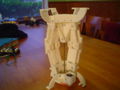
Model Z02 open
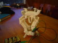
Model Z02 halfway
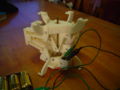
Model Z02 closed
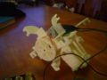
Model Z02 bottom view
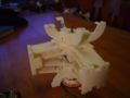
Model Z02 back view


