Rostock Build Manual
Rostock Documentation
Assembly
Motors
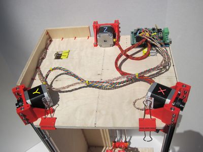
Rostock motors and electronics

- Connect the 3 stepper motors to the X, Y, Z driver outputs on the RAMPS board.
- Maybe add short pieces of colored shrink wrap to identify the motor and endstop cables.
- Red = X: front left motor and endstops (electronics side).
- Yellow = Y: front right motor and endstops (plywood frame side).
- Blue = Z: back middle motor and endstops.
- Adjust the motor voltage (small round potentiometers) on the stepper drivers to 9 o'clock (roughly 30%). This will allow the motors to skip steps in case the endstops don't work. When calibration is done, 10 or 11 o'clock is a good setting to prevent skipping but also avoid overheating the motors and drivers.
- Grabercars says: about 1/8 of a turn clockwise off of minimum power on the Pololu is all it takes to get the motors operating correctly and not making any noise.
Endstops
- Connect the 3 top endstop wires to the XMAX, YMAX, ZMAX connectors on the RAMPS board.
- The endstops are configured "normally connected", so the circuit should be interrupted when the endstop is hit. If your endstops are "normally open", change X_ENDSTOPS_INVERTING to true in Configuration.h.
Belts
It can be challenging to get good belt tension. You should be able to pluck nice bass tones on the belts. Here is Johann's tensioning method:
- Make sure you don't have a flange on the outer idler bearing (the one that is facing you).
- Put timing belt on motor pulley and idler bearings.
- Push idler end up as far as possible with one hand.
- Remove belt from idler bearings.
- Push idler end up 3 mm more and tighten screws on smooth rod.
- Put timing belt on idler again. It will be very tight.
- The idler bearings are tilted 2 degrees upwards, so your belt should not fall off even though the outer bearing has no flange.
- If the belt does fall off, reduce belt tension slightly, or print a new idler end with increased upward tilt.
Calibration

Dial indicator

This section has been updated for the latest modified Marlin firmware (without bottom endstops).
- Download https://github.com/jcrocholl/Marlin and make the following adjustments in Marlin.pde and Configuration.h.
- DELTA_DIAGONAL_ROD 250 mm center-to-center distance of the holes in the diagonal push rods.
- DELTA_SMOOTH_ROD_OFFSET 175 mm horizontal offset from middle of printer to smooth rod center.
- If your print head is too high or low in the middle of the print surface, adjust DELTA_SMOOTH_ROD_OFFSET by half mm and try again.
- DELTA_EFFECTOR_OFFSET 33 mm horizontal offset of the universal joints on the end effector.
- DELTA_CARRIAGE_OFFSET 18 mm horizontal offset of the universal joints on the carriages.
- DELTA_RADIUS (DELTA_SMOOTH_ROD_OFFSET-DELTA_EFFECTOR_OFFSET-DELTA_CARRIAGE_OFFSET) effective horizontal distance bridged by diagonal push rods.
- Z_HOME_POS 402 mm distance between nozzle and print surface after homing.
- If you know the pitch and size of your timing belt pulleys, you can use http://calculator.josefprusa.cz/#MotorStuffSPMB to find the correct value for DEFAULT_AXIS_STEPS_PER_UNIT for X, Y, Z.
- Connect the USB cable to your computer and upload the firmware to the Arduino Mega.
- With the USB cable connected to your computer, start pronterface.py.
- Choose the USB interface, select 250000 baud, click the "Connect" button.
- If the connection is established, you should see some output from Marlin in the window on the right.
- Move the vertical carriages by hand away from all the endstops, so that there is some space above the carriages, and below the print head.
- Place an old book or thick corrugated cardboard on your heated bed or glass surface, to protect it in case of print head crash.
- Connect the 12V power supply. Make sure you can turn it off quickly if the motors are moving in the wrong direction.
- Send the G28 command (home all axes) by clicking on the little house button.
- This should move all 3 carriages up until they hit the top endstops.
- If the carriages start moving down instead of up, turn off the 12V power supply and then reverse the stepper motor connectors on the RAMPS board. Then try again.
- The top endstops are used for micro-calibrating the height of the print bed.
- If you have a dial indicator, you can attach it to the print head with this.
- After G28, move down to the print platform and try horizontal moves in X and Y direction.
- The dial indicator will show if horizontal moves are parallel to the print bed or not.
- Or you can attach a pen and draw lines on paper.
- Or if you already have an extruder and a hotend, print the first layer of a large object.
- If the first layer is too thin near one of the motors, turn the endstop screw in that carriage clockwise.
- If the first layer is too thick near one of the motors, turn the endstop screw in that carriage counter-clockwise.
- One full turn of M3 thread equals 0.5 mm.
- After adjusting endstop screws, send G28 (home all axes) and try again.