RepRap Morgan extended BOM
|
English • العربية • български • català • čeština • Deutsch • Ελληνικά • español • فارسی • français • hrvatski • magyar • italiano • română • 日本語 • 한국어 • lietuvių • Nederlands • norsk • polski • português • русский • Türkçe • українська • 中文(中国大陆) • 中文(台灣) • עברית • azərbaycanca • |
This article is the extended version of a material list for the RepRap Morgan. By Robert Kuhlmann.
Thanks to Quentin Harley for his permission and for his outstanding RepRap Morgan-project.
Contents
Introduction
I've decided to start this page not only to show my Morgan-project, but to enable a seperate development branch of Quentin Harleys outstanding work and to post my ideas without intervening with Quentin's work. I would be honored, of course, if some of the ideas that may evolve over here, finally make it into Quentin's project.
On the other hand I'll try to keep this project up to date with Quentin's progresses and ideas to make this a very progressive and attractive Morgan-project.
This side is still under construction, but I've decided to give it to the public now, because some files and ideas may already be of interest for the community.
You may use all the files and ideas for free and with no restrictions, except of claiming they were your own work. If you want to derive your own Morgan-project from here, feel free to do so, but please let this project go its own path. You can, of course, discuss any aspect on the discussion page here and I'd be very happy and thankful for comments, critics and recommendations.
The parts published here are used in my own RepRap Morgan project. My virtual Morgan has a real brother in a similar state. The virtual Morgan is used as proof for the measurements of the parts in this BOM. While building the virtual Morgan, many corrections on the parts have been done already. If you find mismatches or faults, please let me know, so I can update this BOM and keep it in the best possible state.
News
This section will give some brief information about the last changes.
- Update 08/20/2013:
- News-section established.
- Regarding to an idea in Quentin Harleys forum (Morgan Builders Forum) I designed a new version of the bed-z-mount-bracket to fit with the "Threadless Ball Screw"-project from Mark Sollack (Thingiverse Thing 112718). It raises the vitamin count for the Morgan a bit, but you don't need any threaded rod or trapezoid rod, no anti backlash spring and no z-axis-nuts any more, just 3 small bearings (size 624 or 623), some nuts and screws and one printed part.
- I love that thing, because its as charming as the Morgan itself.
- Update 09/06/2013:
- After Quentin checked the assembly instructions, he noticed some minor flaws, that are corrected now.
- In Detail:
- - The Theta arm b has no 608-bearing hole anymore and therefore the assembly needs one 608-bearing less.
- - There were two extra M8 nuts in the assembly of the PSI arm, that are removed now.
- - As a follow up I had to modify the V3-toolhead.
- The respective files and drawings are all up to date now. Thanks to Quentin for the tips.
Printed parts
You find the original SCAD-file from Quentin Harley, that does all his original parts, over here: Original Morgan SCAD-file
I've redrawn all printed parts to ease modifications for me, because I'm working with Autodesc Inventor.


ZIP-Archives with all files can be downloaded here: All drawings All Inventor files All STL-files
New versions
Here are some suggestions for modifications on the original parts.
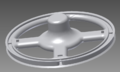
New Drivewheels
Beside a different look, the new design is intended to
- ease montage of the belt. It is sticked into one of the wheel's arms and can be fixed with a cable tie through a hole in the arm.
- offer more possible positions for the end-stop magnets. Instead of separate holes, there's a circular notch, so you can place the magnets in almost any position around the wheel.
- allow better guidance of the belt, for which the entrance to the holes for the belt have rounded edges. This allows a montage of the belt without buckling.
The two models are derived from a common parent-component, adding the different hole-types for their specific role (as PSI/rod- or Theta/tube-wheel).
Drivewheel base/parent ipt


Hardware


I'm using steel- instead of brass- or copper-pipes for the vertical PSI- and Theta-axis, because I can get them in a very slim variant, making them more lightweight, while being more stable and even less expensive, compared to their copper pendants.
<todo> 2mm self tapping coach screws, 40mm
hard spring (idler compression) 7mm
cabinet coach screws, 5mm </todo>
PCB heated bed
I've uploaded my own design of a heated bed here. The archive contains the assembly group and the discrete parts. You need to create an idw-file from "pcb heated bed copper.ipt" to get the layout.
Tips for that:
You should set the line-thickness of the drawing to 0.01mm, color white. If you want a lower resistance with the same layout, just set the line-color back to black.
The hole-marks of the PCB fit with the OpenHW-plate as well as with my own here in the BOM.
The building platform can be fine adjusted with three screws. The usage of more screws for adjustment is optional (not recommended though).
You should isolate the heated bed by covering it with e.g. Polyurethane lacquer. You can then glue it with a thermo conductive adhesive under the top-Platform. Of course this is just a suggestion, if you want to use an aluminum-platform, like I do. Other configurations e.g. with glass need different solutions for platform adjustment and heated bed montage.
Assembly instructions
In this section you'll find detailed instructions on how to assemble the parts to a functioning RepRap Morgan 3D-printer.
Morgan Arm Drive PSI
The 15mm pipe strengthens the threaded rod over its length, so it doesn't bend while printing. The rod alone wouldn't be strong enough. To form the ends of the pipe to hold M8 nuts, just press an M8 nut into the end of the pipe, using an M8 bolt and a small hammer. Use a different M8 nut for the final montage, because the M8 nut may have been damaged by forming the pipe. The result should look like shown in chapter "Hardware". <imagemap> File:Morgan arm drive PSI assembly.png|RepRap Morgan arm drive PSI assembly|300px|center default [1] desc bottom-left </imagemap> Just download the PDF-file by clicking the image. The PDF-file also contains the BOM for the arm drive.
Morgan Arm PSI
The PSI arm is assembled easily. You only have to be careful while pressing the M8 nuts and bearings into the plastic. If it's too tight you should file down the fittings a bit instead of using brute force. Be shure the M8 washers are small enough, so they don't touch the outer part of the bearings. They will block them otherwise. The 28mm washers may be a bit smaller than 28mm. You'll find 24mm washers more easily in your DIY-market. <imagemap> File:Morgan arm PSI assembly and BOM.png|RepRap Morgan arm PSI assembly|300px|center default [2] desc bottom-left </imagemap>
Morgan Arm Theta
Assembling the Theta arm is very simple. You only need to be careful when pressing the bearings in. <imagemap> File:Morgan arm Theta assembly and BOM.png|RepRap Morgan arm Theta assembly|300px|center default [3] desc bottom-left </imagemap>
You can use a 6805 (JIS B 1521) bearing instead of the 61805 (DIN 125). Use what you can buy more easy or cheaper.
Platform adjustment
Here some details about how to adjust the platform (there are several solutions for that, this is just one of them). <imagemap> File:RepRap Morgan Platform Adjustment.png|RepRap Morgan platform adjustment|300px|center default [4] desc bottom-left </imagemap>
Leadscrew nuts and the anti-backlash spring
The two leadscrew nuts and the spring are configured as shown here in the drawing. The tension of the spring against the to nuts reduces the backlash, when the direction of the z-axis-rotation changes. The spring should be app. 26mm long and have an inner diameter of app. 8.5mm to 9mm (9.5mm to 10mm outer diameter). <imagemap> File:Leadscrew nuts and anti-backlash spring montage.png|RepRap Morgan leadscrew nuts and anti-backlash spring|300px|center default [5] desc bottom-left </imagemap>