RepOlaRap
Release status: Concept
| Description | a draft polar RepRap design.
|
| License | unknown
|
| Author | |
| Contributors | |
| Based-on | |
| Categories | |
| CAD Models | |
| External Link |
This is still in draft. I'm just putting down my thoughts and plan to edit it as I proceed with my prototyping:
The Polar RepRap, "RepOlaRap", currently only discusses an X+Y axis robot. I plan on attacking a Z axis once I have a working prototype to test the resolution, positioning accuracy and repeatability, and software complexity for the X+Y.
Contents
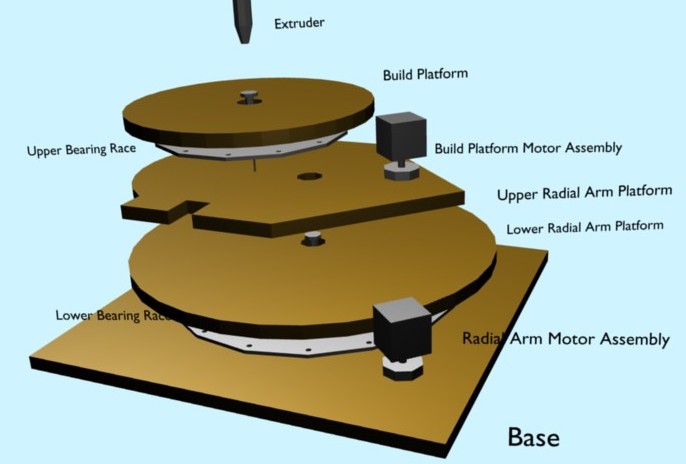
Structural parts from top to bottom
Build platform, 14cm radius disk, 15mm thick (do over = 13mm thick)
- Hole + thrust bearing at center.
- MDF.
- groove for belt placement around perimeter.
2x Bearing Races, disk, 11cm radius, 4mm thick.
- 12x 6mm holes drilled every 30 degrees at 10cm radius
- 4x 6mm holes drilled every 90 degrees at 4cm radius
- 16 5mm stainless steel balls.
- hole drilled at center for bearing bolt.
- One race between build platform and upper radial arm platform.
- One race between lower radial arm platform and base.
Upper Radial Arm Platform, 13mm thick
- general shape is 'house' like structure ~20cm in size.
- MDF.
- hole drilled for interface bolt from thrust bearing on Build Platform.
- hole drilled for build platform bolt.
- One cut out for radial arm bolt + thrust bearing.
- 4 holes drilled and countersunk for screws attaching upper to lower radial arm.
Lower Radial Arm Platform, 21cm radius disk, 15mm thick (do over = 13mm)
- Hole + thrust bearing at center.
- MDF.
- 4 holes drilled, with larger inlays to allow upper/lower attaching nuts to be installed.
- bolted using countersunk machine screws and inlay nuts to upper radial arm.
Base, 46cm x 46cm square, 19mm thick.
- Hole drilled at center for interface bolt from thrust bearing on Radial Arm Platform.
- MDF.
- Cut out for encoder device for absolute radial position of Radial Arm.
Changes I'd make to above based on prototype experience to date
1. Use 13mm for all moving parts to reduce weight. 2. Use inverted bolts (nuts on top surface) to attach lower and upper radial arm platform parts. 3. Cut out the disks AFTER installing the bearing; use the bearing radial capability and a steady pencil to draw the template for cutting. My wheels wobble by 2mm or so; may remake in 13mm, but forging forward for now.
TODO: upload the blender model file for structure.
TODO: Future consideration : counter top laminate for hardness on bearing races. Could not find enough scrap for prototype. Did not want to purchase new because minimum size := too much material for me to justify for cost (I need 2sq feet.. minimum purchase size new was 32sq feet).
TODO: Try using LED/Photo-transistor from http://usdigital.com/products/encoders for encoder assembly, (?as per DCDigitalServomotor?).
Image illustrating XY platform structure:
Model space can be represented as a ring with outer radius of 14cm. The inner radius is defined by the closest approach the extruder can make to the build platform center (typically, this should be < 1mm with proper calibration of the extruder head position.)
Software Strategy
The general strategy for control is to create an N dimensional curve, where each dimension represents an absolute motor position for every motor in the system: Angle1, Angle2, Z, Extruder. Once a representation of the exact curve is produced, a BSpline curve that approximates that curve to within the tolerances needed for each axis. With the B-Spline representation, the knots can then be adjusted in order to solve all of the constraints on velocity, acceleration, and/or jerk, in order to bring them to within 90%-100% of the optimal build speed for the specified constraints.
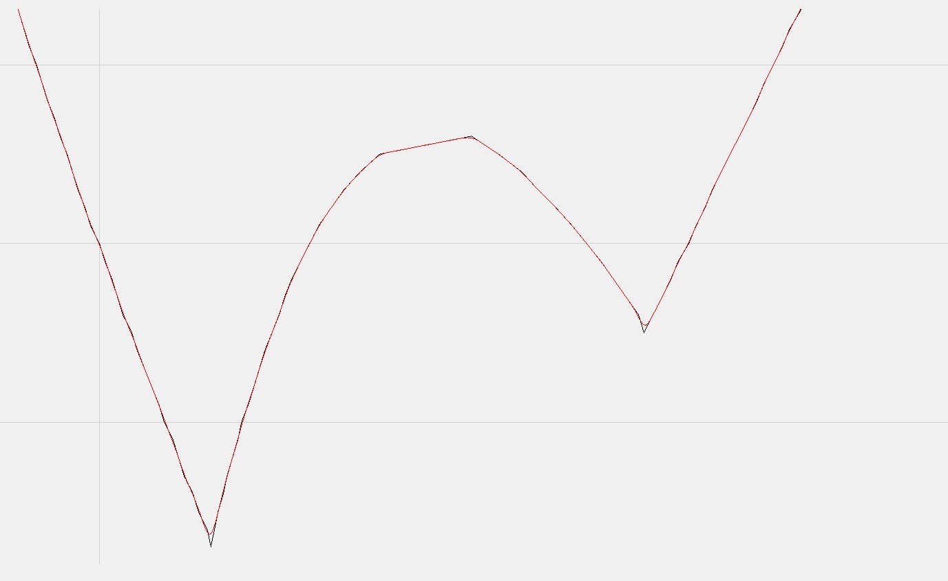
The following image is an example of the B-Spline following one of the axes to a specified accuracy, but before constraints have been solved. Solving the constraints would stretch time at the pointy part of the curve to adjust for maximum jerk or acceleration:
TODO: Calibration -- my thoughts on Builders Blog
I intend to drive the XY platform with closed form inverse kinematics, computed on the host software, and output as a series of stepwise integer splines to the controller firmware. Each step would correspond to some fixed metric, for example, the step pulse send to extrude more filament when extruding, or an arbitrary time unit if simple motion is desired.
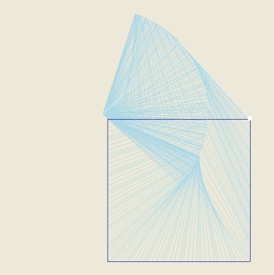
Here is a simulated path for a square from model space (3.5mm,3.5mm) to (98mm,98mm) using cubic splines to represent the inverse kinematic motions along each side in segments, with spline segments no greater than 5mm in length. If you zoom in on the top left corner, you'll see that the line deviates enough from straight to be noticable, as you approach the build platform center, smaller spline lengths (and greater communication overhead) are required to reproduce the inverse kinematics accurately enough.
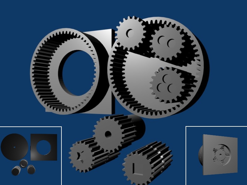
TODO: A second generation RepolaRap might use a gear reduction component to remove the need for belt driven platforms. Mockup in blender as in the following image:
