Reference/SPI LCD
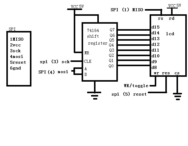
SPI method using shift register. Version 1 draft
It falls within the loose spec of spi. Spi is enabled and disabled in registers after each byte is loaded onto shift register. Shift register acts as a buffer. 1 wr is also the select pin. If wr is set high and not brought low, then the display does not care what the shift register data has. This pin is normally toggled.
If this is the device in communication, then the MISO pin can be set as an output for (rs) reducing pin count. Software sets it back to input when spi is re enabled.
Here is some of the code, however there is another method I’m working on that is much faster.
here is a link to the code that is being worked on for this. version 0.3c works with spi interface above.
