PowerCode
|
English • العربية • български • català • čeština • Deutsch • Ελληνικά • español • فارسی • français • hrvatski • magyar • italiano • română • 日本語 • 한국어 • lietuvių • Nederlands • norsk • polski • português • русский • Türkçe • українська • 中文(中国大陆) • 中文(台灣) • עברית • azərbaycanca • |
Release status: working
| Description | |
| License | Creative commons, atribution, share alike.
|
| Author | |
| Contributors | |
| Based-on | |
| Categories | |
| CAD Models | [[File:]]
|
| External Link |
I start doing the Power Code wiki, I'll work as I have some time, as for now I will put the links to Google + to try to collect on this wiki everything about this printer model .
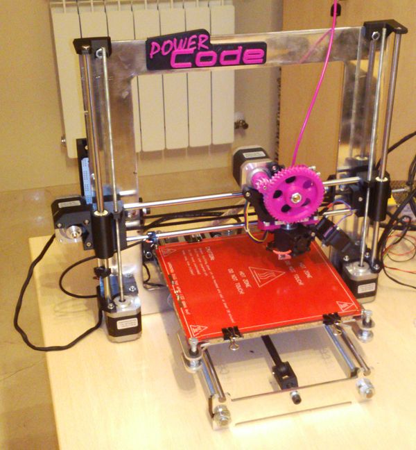
As you can see the design is largely based on the Prusa I3 . What I like about this design is its simplicity, its balance between functionality and self-replicating and its tremendous accessibility to modify or improve but also to understand and explain.
I was particularly struck by the implementation of the X axis with vertical guides and very compact (especially when compared with the previous Prusa and Mendel ). Apart from these features perhaps the most determinant is increased Z-axis travel, in previous versions were below 150 mm and in this can exced 200 mm . We could say that we entered in the category of 8000 cm3.
Here is the link to the Prusa I3 that I made:
https://plus.google.com/u/0/photos/103202626711995973200/albums/5874632687787268257
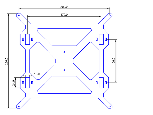
At the root of this I decided to make my own version of this design, the Google+ post said : I will build another Prusa I3 but this time I would like to make it more personalized . The first thing I will change is the platform , I feel better with 4 linear bearings . A part of it going to increase the separation between the bearings of the same rod to increase stability . In the original design is 70 mm , I've had to 100mm. This change causes the Y-axis bars , have to be longer but I don’t care , I calculated initially 390mm for M10 rods and 370 for plain bars.
On the other hand I would like to remove the threaded rods on the front and back of the printer. I want to replace these for flat parts laser cut aluminum. When you cut the Prusa I3 frame with platform inside, plenty much material that I'm sure we charge, therefore, the new pieces must enter in that area.
This will be the first I3 rod mount with M10 , I hope it is more robust than the M8 rod I put in the previous one, but anyway I'm thinking of having a reinforcement, a bar that goes from the frame to the backpiece to form a triangle and to give rigidity. In fact I think if I have the bars , I will let down the aluminum thickness to 5mm. These bars, and front and rear parts also going from the material inside the frame.
Another of the problems I encountered when I rode the I3 was that the belts were not tight and was hard tighten them. For the new design would have belt tensioners on both axes.
https://plus.google.com/103202626711995973200/posts/8uHMkRuMrxe
https://plus.google.com/u/0/photos/103202626711995973200/albums/5892363097748768993
And finally I finished this design:
https://plus.google.com/103202626711995973200/posts/QuXqXbYihkt
I designed this logo :
https://plus.google.com/103202626711995973200/posts/YydR8RPpM6s
And this is my machine :
https://plus.google.com/u/0/photos/103202626711995973200/albums/posts
This could say it's the first version, the next version we see in the magnificent photos of F Malpartida :
https://plus.google.com/105302838626030917261/posts/hhJh6iKJ9br
A photo collection assembly can be viewed at:
https://plus.google.com/103202626711995973200/posts/aMDSBgx6qcB
All parts , BOM and Power regarding the Code you can see it on github :


