McWire Cartesian Bot 1 2 (Death March: Do not build!!!)
Contents
- 1 McWire is a Death March. Do not build one. You have been warned! :D
- 2 This project is no longer actively developed.
For newer mcwire infopost-mortum ashes-sifting, please see Development:McWire - 3 McWire Cartesian Bot v1.2
- 3.1 Introduction
- 3.2 Get It!
- 3.3 Prepare Raw Materials
- 3.4 Preparatory Work
- 3.5 Assemble Bearing Arms
- 3.6 Attach Fixed Bearings
- 3.7 Attach Bearing Arms
- 3.8 Attach Captive Nut
- 3.9 Assemble Machine
- 3.10 Test and Calibrate
- 3.11 Start Printing
McWire is a Death March. Do not build one. You have been warned! :D
<sebastienb> Think anyone will complain if I move
<sebastienb> http://reprap.org/wiki/McWire_Cartesian_Bot_1_2
<sebastienb> to
<sebastienb> http://reprap.org/wiki/McWire_Cartesian_Bot_1_2_(Death_March: Do not build!!!)
<chronomex> haha
<tesla893> i built a mcwire :(
<sebastienb> Page moved.
Please build a nice Eiffel, T-Slot, or WolfStrap-English instead.
This project is no longer actively developed. For newer mcwire info post-mortum ashes-sifting, please see Development:McWire
McWire Cartesian Bot v1.2
Introduction
Many more pictures of the machine can be found by clicking an image, or visiting the Flickr photo gallery.

This design is based on a previous design by Tom McGuire, and was named after him. We have since taken his design and improved upon it in a few crucial areas and adapted it for our particular needs. We are very grateful and appreciate the hard work he put in. All of our subsequent work is released under the GPL.
Purpose
The McWire Cartesian Bot is a 3 axis cartesian robot designed for light milling, additive 3D printing, laser cutting / etching, and pen plotting. The design strategy has focused on ease of construction, maintenance, and operation. We also tried our hardest to minimize cost while providing a robust 3D positioning system. The result is a machine that provides smooth, high quality motion while keeping costs under $250. We hope you enjoy this project as much as we have.
Files
This design is based on drawings. Nearly every single part has been drawn with a program called QCad. All of the files are released under the GPL license. There are two ways to get the files: you can check them out of subversion, or you can download the release file from Sourceforge. The release file has extra goodies like printable PDF templates for you to use.
- Download the files from SourceForge.
- Subversion: svn co http://reprap.svn.sourceforge.net/svnroot/reprap/trunk/users/hoeken/mcwire-cartesian-bot
Operational Theory
The basic operation of the cartesian bot is that there are 3 'stages', or 'axes' that each move in a different direction. Looking from the front of the machine, the X Stage moves left to right, the Y Stage moves front to back, and the Z Stage moves up and down. Each stage is driven by a 'leadscrew'. What this means is that a nut is attached to each stage so that it cannot rotate. A length of threaded rod is run through the nut and attached to a motor. When the motor turns the threaded rod it forces the nut (as well as the stage) to move in one direction. The combination of all 3 axes allows us to position a tool head at any arbitrary point in 3 dimensional space.
Get It!
Prepare Raw Materials
There are a variety of raw materials you will need to construct your bot. Its a good idea to get all of them on hand before you assemble your machine just to make sure you have everything. Trust me, theres nothing more frustrating than assembling all the components and realizing you are missing one minor part that makes it all work.
Tools Required
At the minimum, you will need the following:
- Drill press, although you could get by with a power drill.
- Power Drill
- Screwdriver
- Hacksaw
- Pliers
- Pipe wrench
- Scissors
- Printer
- A vise
- Sandpaper: rough, medium, and fine
If you are making your own acrylic sheets, you will need:
- A jigsaw, or other tool to cut curves.
- A special countersinking bit (available from McMaster, part number 2846A35, 82 degree angle)
Bill of Materials
You should refer to our online parts lister that has details on the parts needed, as well as where to get them. We also have the parts listed on a Google spreadsheet that is embedded below.
<iframe width='550' height='800' frameborder='0' src='http://spreadsheets.google.com/pub?key=pmEMxYRcQzzATwbOb71BmGA&output=html&gid=22&single=true&widget=true'></iframe>
Structural Components
<div class="thumb tright"></div>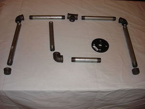
The main structure of the bot is made from 3/4" steel pipe. This is the same kind of pipe used for plumbing. It is relatively cheap, easy to find, and easy to assemble. Pictured below are all the parts required to assemble it (note: pipe sizes may change from picture.)
Aluminum Rails
<div class="thumb tright"></div>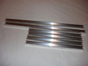
The aluminum rails provide 2 important functions: they ensure that the stage moves in a straight direction and only that direction, as well as providing a bearing surface to handle the load of the stage. You will need 2 rails per axis, and a grand total of 6 rails.
Aluminum Supports
<div class="thumb tright"></div>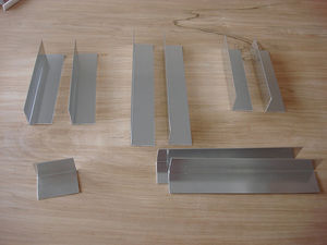
For added rigidity of the aluminum rails, as well as a convenient place to mount the stepper motors and endstop switches, we use lengths of 90 degree aluminum angle. Each piece of aluminum is bolted to the ends of the aluminum rails. The stepper motors are then bolted to these supports, as are the optical endstops. A convenient side effect of this is that the entire aluminum rail assembly acts as a heat sink for the stepper motors, allowing them to run at very low temperatures.
Note: the supports pictured are 1/16" thickness. It's highly recommended to use 1/8" thickness from McMaster.com
Acrylic Cutouts
<div class="thumb tright"></div>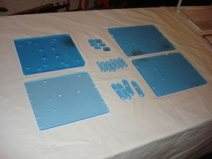
The most complicated part of the system are the acrylic pieces. For your convenience, the RRRF will be doing a bulk order of lasercut pieces. If you prefer to create your own pieces, the digital files used to create them are available. You could either have them lasercut yourself, or you are skilled enough, you could print them onto a full page sticker, place the sticker on acrylic, wood, or some other flat piece and then cut/drill in the appropriate places. The design has intentionally kept each piece small enough that it could fit onto a 8.5" x 11" sheet of paper.
(Note: pictured here are the cutouts with blue protective backing.)
Teflon Bearings
<div class="thumb tright"></div>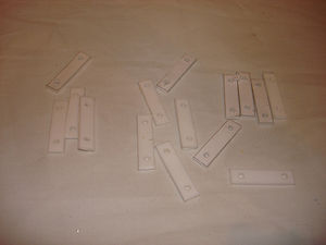
The teflon bearings are one of the major improvements made to the original design by Tom McGuire. Teflon has the lowest coefficient of friction of any plastic, and is ideally suited as a bearing material. It turns out that McMaster supplies teflon in 1/2" long strips which are easily made into bearings. Simply cut them to length, drill a hole on each side and then attach them to the stage with screws. We've even provided a sticker template that will help you drill the holes in the proper place.
Springs
<div class="thumb tright"></div>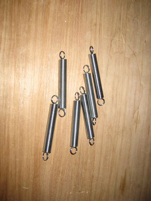
You'll need various springs to keep the different parts of the machine in contact and such. In some parts they keep the bearing arms pulled together which keeps the stages pressed up against the aluminum rails. On the Z axis, they also keep the Z Stage pressed up against the rails, as well as provide a counteraction to gravity to reduce missed steps and lessen the force on the Z stage motor and coupling.
Leadscrews
<div class="thumb tright"></div>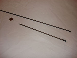
The leadscrews are the part of the system that drives each stage. Some systems use leadscrews that cost as much as our entire machine, but instead we use simple 1/4"-20 threaded rod that you can find at a hardware store. We order it from McMaster which means its usually very straight. If you buy it from a local hardware store, make sure you spend some time looking along the length of the rod to make sure it is straight. This is one of the single most important parts to make your machine run smoothly.
For the best results, its recommended you use high quality stainless steel threaded rod from McMaster because it will wear less, and generally be straighter than your average battered hardware store rod.
Roller Bearings
<div class="thumb tright"></div>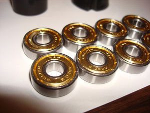
The roller bearings fulfill a variety of functions, but primarily they allow the machine to run smoothly. Along with the springs, they also ensure that the stages are all tight up against the rails they run on. We've decided to use standard skate wheel bearings. They are cheap, ubiquitous, high quality and awesome. Whats more steampunk than going into a local skate shop and pick up a set of skate bearings to build your self-replicating robot? A bunch are pictured below.
Various Fasteners
[ <img src="" align="right"/>]
You will need various nuts, bolts, washers, and screws to assemble your machine. We have listed them all in the bill of materials and the picture to the right should theoretically be all the parts you need. It wouldn't hurt to have extras on hand since its easy to drop a nut and lose it.
Preparatory Work
Cut Aluminum Rails To Length
<div class="thumb tright"></div>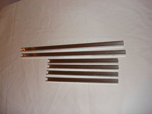
You will need to cut your rails to the specified lengths. I recommend using a hacksaw and some clamps. Cut slowly and you can be very precise. Cut from the bottom of the U to the top. Remember: measure twice, cut once!
- X Rails (2) - 21 inches
- Y Rails (2) - 13 inches
- Z Rails (2) - 13 inches
Once you have cut them to length, its a good idea to use a file to remove the burrs from the ends of the rails. Be careful not to damage the top bearing surfaces!
Cut Aluminum Angle to Length
<div class="thumb tright"></div>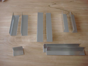
- X Supports (2) - about 6 3/8 inches (6.33" to be exact)
- Y Supports (2) - about 9 1/16 inches (9.074" to be exact)
- Z Supports (2) - about 5 15/16 inches (5.90" to be exact)
- Extruder Mount (1) - 2.5 inches
- Bearing Arm Mounts (2) - 9 inches
Drill Support Holes
<div class="thumb tright"></div>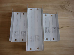
Take the support stickers, and apply them to the top side of the supports. Take care to carefully apply them so that they are well aligned with the edges. it is mostly important to align the front of the sticker template with the front of the support. Once you have the stickers attached, carefully drill out the indicated holes. Drill the two large holes out at 5/16", and drill the two small optical endstop mounting holes out at 1/8".
Cut Threaded Rod to Length
[ <img src="" align="right"/>]
The best way to cut small threaded rod like this is with a Dremel and a cutoff wheel. If that is not available, a hacksaw and a clamp will work. Take care not to bend the rods or damage the threads. Also, its a good idea to put a nut on the rod before you cut it, so that you can 'fix' the threads at the cut end by unscrewing the nut. Do not cut through the nut itself!!!
- X Leadscrew (1) - 19 inches
- Y Leadscrew (1) - 11 inches
- Z Leadscrew (1) - 9 inches
Countersink the Acrylic Cutouts
<div class="thumb tright"></div>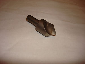
In order to get the proper clearances from the mounting hardware, various mounting holes need to be countersunk. This means you use an angled drill bit that drills the acrylic so that the top of the screws sit flush with the surface of the acrylic. If you get the lasercut boards from the RRRF, this will already be done for you. If you build your own, you will need to do it yourself. The pictures below show each piece to be countersunk, as well as which side to do the countersinking on. Be careful to do it on the side that needs it, as it is important which side you do it to.
The proper bit is available from McMaster, part number 2846A35. You need a countersink with an 82 degree angle.
Bearing Arm
<div class="thumb tright"></div>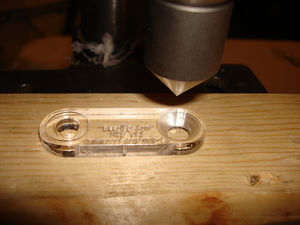
Only one of the holes needs to be countersunk. There is a larger laser-etched circle which marks how deep the countersink needs to be.
Vertical Bearing Arm
<div class="thumb tright"></div>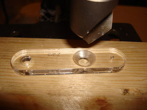
This has one hole in the middle to be countersunk. There is another laser-etch guide circle. Countersink it to that size.
X Stage
<div class="thumb tright"></div>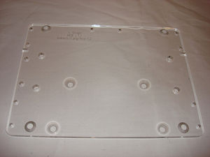
This one is tricky. There are 8 holes to be countersunk, 4 on each side.
Four holes need to be countersunk from the bottom. These holes are the large ones near the corners. They are for mounting the Y Rails. They have no depth markings, you'll have to eyeball it.
Four holes need to be countersunk on the top. These holes are for the bearings. They all have countersink indicator circles.
Y Stage
<div class="thumb tright"></div>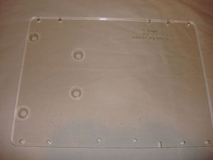
This one is easy. There are 4 holes to be countersunk, all from the top. They each have indicator circles.
Z Stage
<div class="thumb tright"></div>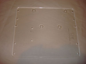
This one is easy too. There are 4 holes to be countersunk, all from the top. They each have indicator circles.
Note: In the picture, the indicator circles are too big, but this is fixed in the production drawings.
Vertical Base
<div class="thumb tright"></div>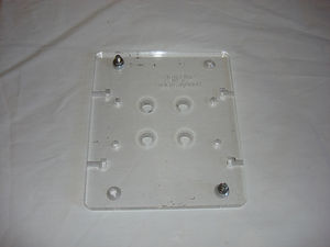
This one is tricky, but is similar to the X Stage. There are 8 holes to be countersunk, 4 on top, 4 on bottom.
The top holes have large countersink indicators. These are for larger screws to mount the base to the pipe flange.
The bottom holes are small, and have no indicators. They are on the corner and should be countersunk for the normal, 5/16" bolts. These are for mounting the Z Rails.
Cut PTFE Bearings
<div class="thumb tright"></div>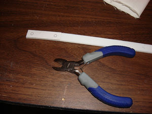
Making the PTFE Bearings is very easy! Simply cut out a bunch (12) of the stickers in stickers/ptfe-bearings.pdf. Then, get out your strip of strip of PTFE and apply one sticker to it. Use a pair of wire cutters to cut the PTFE strip at the end of the sticker. Repeat until you have 12 sticker coated strips of PTFE.
Drill PTFE Bearings
<div class="thumb tright"></div>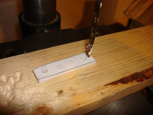
Once you have all your PTFE bearings cut, you need to drill them out. This is pretty easy too. The stickers all have holes on them. Drill these holes out with the appropriate drill bit (3/16"?) When you're done, you can optionally remove all the stickers. They should come off the PTFE really easily.
Attach PTFE Bearings
Once you have your PTFE bearings, its time to attach them to the stages. Each stage gets 4 bearings: one on each corner. There are two small mounting holes on the corner of each stage that match up with the holes you just drilled. Line up the bearings and use the 10-24 thread cutting screws to attach them to the bottom of the stage. If you use a power drill, turn the torque limit all the way down so you dont over-drill and break the acrylic or damage the bearing.
X Stage
<div class="thumb tright"></div>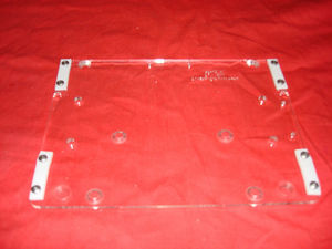
Y Stage
<div class="thumb tright"></div>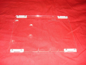
Z Stage
<div class="thumb tright"></div>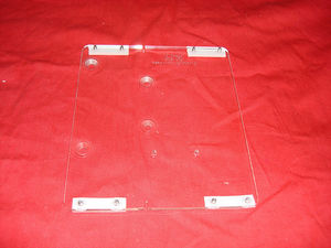
Assemble Bearing Arms
Attach Bearings
<div class="thumb tright"></div>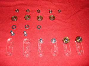
First, attach the bearings with nuts, bolts, and washers. The picture shows the various stages.
Insert Nail
<div class="thumb tright"></div>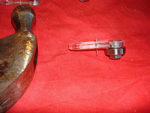
Next, take a small nail and hammer it through the small hole in the middle of the bearing. Take care not to break the bearing. If you bend the nail, use a new one.
Trim and Bend Nails
<div class="thumb tright"></div>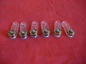
Finally, cut the sharp end off each nail with the wire cutters. Next, bend each of the nails to 90 degrees. Each set of bearings needs to be bent in opposite directions.
Attach Fixed Bearings
<div class="thumb tright"></div>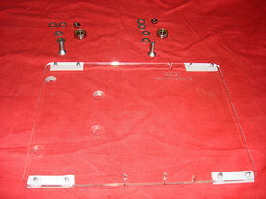
Each stage has 2 fixed bearings that are used to keep the stage traveling in the direction of the axis, and not perpendicular. These are simple to attach. You'll need some washers, some 1" long 5/16" bolts, some nuts, and some bearings.
X Stage
<div class="thumb tright"></div>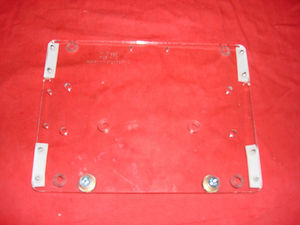
Y Stage
<div class="thumb tright"></div>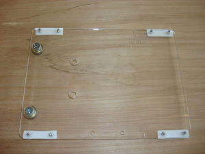
Z Stage
<div class="thumb tright"></div>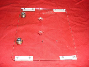
Attach Bearing Arms
<div class="thumb tright"></div>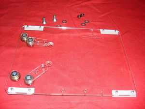
The bearing arms are adjustable and used to keep the stage pressed up against the rail. The bearing arms press against the rail, forcing the stage to move until the fixed bearings contact the rail. In doing so, they force the stage to move in a straight line. When you attach them to the stage, the do not need to be aligned, that will happen in a later step. We are simply attaching them for now.
It is important however to mount them so the bent nails are facing away from each other.
X Stage
<div class="thumb tright"></div>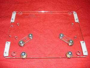
Y Stage
<div class="thumb tright"></div>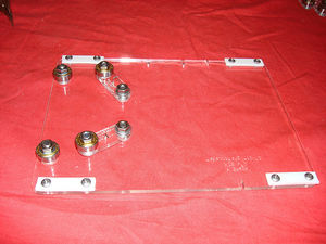
Z Stage
<div class="thumb tright"></div>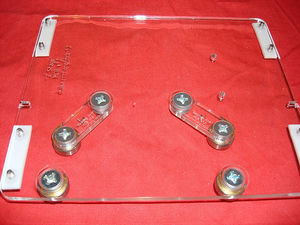
Attach Captive Nut
<div class="thumb tright"></div>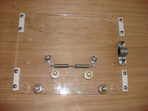
The captive nut is a nut that is attached to the stage. When the drive screw rotates, the nut (which is fixed) will move up or down, dragging the stage along with it. This is how we convert the rotary motion of the drive screw to a linear motion.
Attaching the nut is easy. Take one nut and a U bracket. If your U bracket is larger than the nut, simply take some electrical tape and wrap it around the nut until there is a snug fit. Not too much, not too little. You'll have to eyeball it.
Once you have that done, attach the nut to the stage with the U channel with either 10-24 x 3/4" self-tapping screws, or some M3 bolts + nuts.
The process is very similar for both the X, Y, and Z axes. The mounting points are:
- X axis: left side
- Y axis: top side
- Z axis: near the bottom
Assemble Machine
Structure
<div class="thumb tright"></div>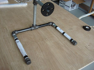
Once you have everything ready, you will want to start by assembling the pipes. I like to start with the base and work my way up to the vertical components. Here is the order I generally use:
- Put the pipe caps on the 12" pipes.
- Put the 90 degree elbows on the 12" pipes.
- Put a 6" pipe on one of the elbows.
- Put the 3 way tee on the 6" pipe.
- Put another 6" pipe on the other end of the tee.
- Flip it up and screw on the other 12" pipe assembly.
- Put the remaining 12" pipe in the vertical part of the tee.
- Put the elbow on the top of the 12" pipe.
- Put the 3" pipe in the other end of the elbow.
- Put the flange on the end of the 3" pipe.
Once you have them all assembled, you will need to tighten them and get them all in the proper positions. you can push on opposite corners of the 'square' formed by the bottom parts to get it to lay flat, and can use your pipe wrench to get the other pieces tight. Once you have a feel for how everything works, you may want to undo everything and then re-assemble it using thread locker to make the pipes stay in position better. You may want to delay this until the very end so that you make sure the whole thing works properly.
Also, don't put thread locker onto the flange just yet, you need to attach the Vertical Base and align it before you make it permanent. Do not put thread locker onto the 'legs' of the base either, you'll need to remove those in order to drill them.
Note: this picture is with the old pipe lengths. The structure is exactly the same though.
X Axis
This is the base of the machine. The X axis carries that Y axis which also eventually holds the build area.
X Rails
Now that you have the structure assembled, you will want to start by assembling the X Stage. We have provided a PDF printout that you can print onto a sticker, cut out, and apply to the pipes that will provide you with guides of where to drill into the pipe to mount the X stage rails. Its highly recommended that you use these stickers. It will make your life easier, and make your machine work better.
Attach Pipe Stickers
<div class="thumb tright"></div>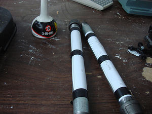
Cut out the stickers, and be careful to not cut on the lines. Once you have them cut out, cut along the line on one end of each of the stickers you just cut. Be very precise when you do this. You will then take this edge and line it up with the pipe where the threads end. Apply the sticker along the length of the pipe on the top. When you have applied both stickers, you will want to prepare the holes for drilling. Take a center punch (or sharp screw/nail) and use it to make a small indentation in the center of the holes where it shows you to.
Drill Pipes
<div class="thumb tright"></div>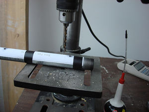
After you have made the indentations, ideally remove the pipes and take them to your drill press. If you do not have a drill press, keep them attached and get your power drill. You will want to drill through the pipes with a x/x" drill bit. It is a good idea to use cutting oil (3-in-1 oil works just fine) Place a bit of oil on the spot to be drilled and begin drilling. Do not force the drill to much and take your time. The pipes are actually relatively easy to drill through if you have a decent drill bit.
First Rail Drillings
<div class="thumb tright"></div>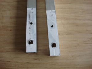
Now it is time to assemble the frame stage. The rails are too big to have one sticker fit onto one page. Instead, we have provided a sticker that you can apply to one end of the rails to drill reference holes, then the rest of the holes can be drilled by using various tricks and techniques like visual comparison. Cut out the X stickers and apply them to the ends of the X rails. Drill the holes as they are marked.
Attach, Mark, and Drill Rails
<div class="thumb tright"></div>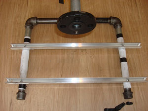
Once you have drilled the aluminum rails, its time to attach them to the steel pipes. Get some of the 3/4" thread cutting screws out, as well as your power drill. You can do it with a normal screwdriver, but it does take a decent amount of force to cut threads into the steel pipes. Give it some juice, and soon you will have firmly attached aluminum rails. Since you only drilled one side of the holes, its now time to mark on the other side of the rail where to drill to attach the rails to the other pipe. Use a marker and estimate where the hole will be. A line down the pipe template has been provided to help you mark in the correct spot. While you're at it, you should mark the holes for the far support. Take the appropriate X support and hold it up to the rails. Stick a marker through the holes to mark where to drill the rails to attach the support. Finally, remove the rails, drill them, then re-attach everything.
Drill X Rails (2nd Time)
<div class="thumb tright"></div>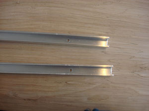
Drill the holes out where you marked to attach the rails to the other side of the pipes. Once you're done, attach both ends of each rail to the pipes.
Attach Motor Supports
<div class="thumb tright"></div>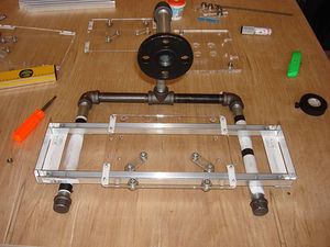
Now that you have the rails attached, its time to attach the motor supports. The support on the left side should have predrilled holes. However, the support on the right side will need to be marked and drilled. Take one of the supports you have predrilled, hold it up to the rails, and mark (through the hole) in the middle of each rail.
Take the rails off again, drill the marked holes out to 5/16". Then re-attach the rails.
Finally, you will want to attach the supports to the rails. Take some of the 5/16" hex head bolts, and some 5/16" nuts. Insert the bolts and nuts and tighten them to attach the supports. The nut should fit exactly in the U channel and you should simply have to turn the bolt to tighten it.
Do not fully tighten it, as you'll need to remove it in the next step.
Attach X Axis Motor

First, lay the X stage on the rails. You'll want a spring adding tension between the bearing arms so that the stage is held firmly up against the front rail.
Next you'll need to get the X threaded rod. Thread the rod through the drive nut, about an inch deep. You'll be marking where to mount the stepper motors. Slide the stage so that the free end of drive screw touches the motor mount. Align the drive screw so it is parallel with the rails, as well as parallel with the stage it is driving. Mark where the drive screw hits the motor support with a sharpie.
Remove the motor support, and print out a NEMA 23 motor sticker. Cut out a sticker, and line it up with your mark for the drive rod. Attach the sticker to the motor mount. Keep in mind that you should mount the motor diagonally. One corner of the motor should stick above the support, and one below. Two corners should be in the middle of the support.
Next, drill out the holes on the motor mount. Use a 7/16" bit on each of the holes. Re-attach the motor mount to the rails.
Finally, mount the motor to the motor mount (say that 3 times fast!). Use M5 x 20 bolts. Make sure that the drive shaft from the motor does not touch the side of the hole. Also, its a good idea to use a couple washers to fill the gap between the motor and the support caused by the large raised circle on the face of the motor.
Attach Drive Screw to Motor
<div class="thumb tright"></div>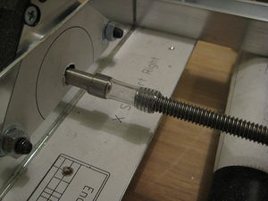
Cut a short (20mm) section of aquarium tubing, or other tubing that has a 1/4" ID. Take a philipps head screw driver to stretch each end of the tubing for easy attachment. First, thread the threaded rod into the tubing with your fingers. Tighten it a bit with some pliers (but dont mangle it!) Secondly, using the rod, push the tubing onto the end of the stepper motor. Finally, once the stepper motor is attached to the rod, rotate the motor by hand and make sure the tubing is centered on the motor.
Rotate the motor a bit with your fingers and marvel at how your stage moves!
Attach Limit Switches
[ <img src="" align="right">]
At this stage, you can also attach the limit switches. Take the limit switches, a limit switch spacer, and bolt the whole assembly to each support. Take care not to pinch any wires, nor to tighten the bolts too much that you damage the limit switch. I generally just hand tighten them, then use a bit of tool tightening to make sure they don't rattle off.
Y Stage
Attach Y Rails to X Stage
<div class="thumb tright"></div>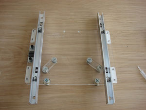
The Y Rails bolt onto the X stage. The rails should have been drilled in the preparation steps. Don't tighten them too much.
Attach Y Motor Mounts to Y Rails
<div class="thumb tright"></div>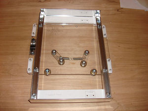
The Y supports bolt on as well. The process is the same as bolting on the X motor supports.
Mount Y Motor
<div class="thumb tright"></div>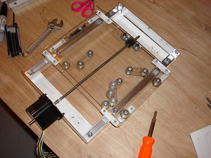
Attaching the Y motor is very similar to attaching the X motor. It should face the front of the machine.
Z Stage
Attach Z Rails to Vertical Base
<div class="thumb tright"></div>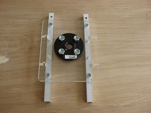
Bolt the Z rails into the top of the vertical base. Align the rails with the bottom holes, and mark where to drill the 2nd set of holes. Unbolt the Z rails, drill them out, then re-mount them with all 4 bolts.
You can either bolt the flange to the stage, or attach the flange to the stage and bolt the stage to the fully assembled pipe stage. Same diff.
Attach Z Motor Supports to Z Rails
<div class="thumb tright"></div>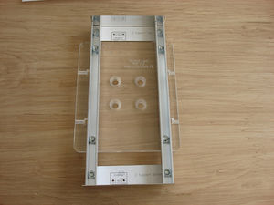
Attaching the supports to the Z rails is basically the same as the X/Y rail supports.
Mount Z Motor
<div class="thumb tright"></div>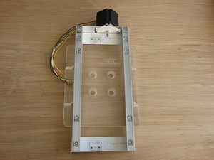
Attaching the Z motor to the Z rails follows the same pattern as the X and Y motor. Have fun!
Attach Vertical Bearing Supports
<div class="thumb tright"></div>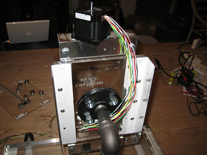
You can attach the vertical bearing supports with either some self-tapping screws, or some M3 bolts. These pieces are what you attach the bearing arms to.
Attach Vertical Bearing Arms
<div class="thumb tright"></div>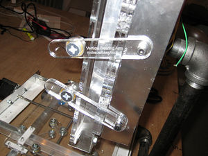
The bearing arms need to be attached so that they can be pulled together with a spring in order to keep the Z stage pressed up against the rails. A good method is to hold the Z Stage to the Z Rails with a strong rubber band. Move the stage to the bottom support and place a vertical bearing at the top of the Z stage so that the bearing is on the stage, and the mounting point is almost 90 degrees to the stage (but not quite). Mark where to mount the bearing arm.
Move the stage to the top and repeat, but with the bearing placed at the bottom of the Z stage.
Electronics
You can drive this system with any electronics you like, but the RepRap team has developed various open source electronics systems that you can use.
Continue reading about the electronics systems or skip to the recommended Arduino based electronics.
Once you have the electronics, the easiest method of mounting things is to mount all the large boards (Stepper Drivers, PWM Driver, DC Motor Driver, Arduino) to a thin piece of plywood. Then take this board and zip-tie it to the back of the pipes. You can then run wires to the stepper motors / opto endstops / extruder(s).
Attach Extruder
Attaching the extruder is easy. Take a short length (2-3") of the aluminum angle. Drill a couple holes in the top and bottom of it. You'll want to bolt your extruder to it, so drill the bottom holes to match your extruder. Bolt the extruder to the aluminum angle, and place it on the Z stage as if you were mounting it. Make sure the Z stage is as high as it will go (home position) Position the extruder so that the extruder tip extends just below the lower Z rail support. Mark the place where the extruder mount is located. Mark the Z stage through the holes in the extruder mount with a sharpie. Make sure they are not above any components such as the drive screw. Take the Z stage off, drill the extruder mount holes you just marked, then bolt it all together.
Your extruder is now mounted. =)
Test and Calibrate
Exerciser Firmware
RepRap Host Software
It is pretty easy to get the McWire bot to work properly with ReplicatorG, this being said you will need the Makerbot firmware loaded onto your electronics. To do this simply open your Machines.xml file in a text editor and add this at the end of the file (but insert it before the </machines> tag)
<machine>
		<name>McWire CNC</name>
		<geometry type="cartesian">
			<!-- different pulleys on X and Y axii -->
			<axis id="x" length="80" maxfeedrate="460" scale="314.9606"/>
			<axis id="y" length="220" maxfeedrate="460" scale="314.9606"/>
			<axis id="z" length="60" maxfeedrate="225" scale="314.9606"/>
		</geometry>
		<tools>
			<tool name="Pinch Wheel Extruder v1.1" type="extruder" material="abs" motor="true" floodcoolant="false" mistcoolant="false" fan="true" valve="false" heatedplatform="true" collet="false" heater="true"/>
		</tools>
		<clamps></clamps>
		<driver name="sanguino3g">
			<!-- optional, defaults to first serial port found.    <portname>COM1</portname> -->
			<portname>COM4</portname>
			<!-- required: we need 8 bit and 38400 baud. -->
			<rate>38400</rate>

			<parity>8</parity>
			<!-- optional, defaults to 1.                          <databits>1</databits> -->
			<!-- optional, defaults to N.                          <stopbits>N</stopbits> -->
                        <debuglevel>0</debuglevel>
                        </driver>
                        <warmup>
                        </warmup>
                        <cooldown>
                         M18
                        </cooldown>
</machine>
You may have to change the maxfeedrate value if you choose smaller stepper motors, but this will slow down your printing and typically cause lower quality prints. Theoretically, you can set maxfeedrate higher, but in my experience it was unstable and cause some steps to skip, ruining the print.
Now when you open ReplicatorG there should be a new machine under the "Machines drop menu" select it and hopefully it will connect to your machine!
Start Printing
MiniMug
External Reference
More build notes: [1]