LongboatPrusaBatch1
Contents
Assembly
Alternative build guides
There is also a great blog by Brian here detailing the build of his Longboat Prusa, with lots a photos.
Frame assembly
In this section we will be looking at the frame assembly.
NOTE: Even if you have assembled a RepRap Prusa before please read these instructions as our frame differers slightly from the standard Prusa.
Tools
30cm rule
M8 Spanner
Step 1 Frame triangles
Components
- 4x Frame Vertex with foot
- 2x Frame Vertex
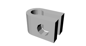
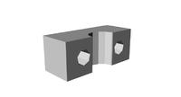
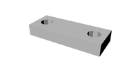
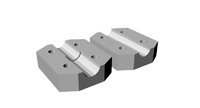
- 2x Bar clamps


- 6x 370mm M8 Threaded rod
- 28x M8 Nuts Bag 1
- 28x M8 Washers Bag 2
Instructions
Divide the above components in to two even sets.
Take one of the lengths of threaded rod and slide a bar clamp to the middle. Place a washer and then a nut either side of the clamp.

Place a nut, washer and then a frame vertex with foot followed by a washer and the nut on to each end of the rod. Loosely tighten the nuts.


Attach two more lengths of threaded rod to each footed frame vertex, using a washer and nut either side as before.


Attach a non footed frame vertex to the connect up the triangle.
Repeat all the above instructions until you have two matching frame triangles.

Place each frame flat on you desk, using your ruler tighten the nuts until each side is 290mm (measure from plastic to plastic)

Step 2 Cross Bars
Components
- 4x Bar clamps
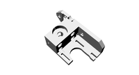
- 1x Y Motor bracket

- 2x 608zz Bearings
- 4x 294mm M8 Threaded rod
- 14x M8 Nuts Bag1
- 15x M8 Washers Bag2
- 4x M8 Mudguard Washers Bag 3
Instructions
Take the Y motor mount and attach a 294mm length of rod through the bottom hole, approximately half way along the rod. Fix in place with a M8 washer and M8 nut either side.

Take a Bar clamp and attach in to a 294mm length of rod, approximately a quarter of the way in from one end. Fix in place with a M8 washer and M8 nut either side. Then attach a M8 nut and M8 washer half way down the rod. Attach this rod through the top hole of the Y motor mount.

Add the following components, a M8 Mudguard washer, M8 washer, 608zz bearing, M8 washer, M8 Mudguard washer and then a nut.

Add a bar clamp to the rod attaching with a M8 washer and M8 nut either side.

On a new 294mm length of rod attach a 608zz bearing, followed by a M8 washer, M8 Mudguard washer and M8 nut either side. Attach the remaining two bar claps either side of this, attaching with M8 washers and M8 nuts either side.

Step 3 Frame assembly and jigging
Components
- 26x M8 Nuts
- 24x M8 Washers
- 3x 440mm Threaded Rod
Instructions
Take the rod assembly which has the two rods held apart by the Y motor mount, add a M8 nut followed by a M8 washer.

Take one of the frame triangles made earlier and attach the Y motor mount rod assembly through the holes in the frame vertex with foot. Attach in place with M8 washers and M8 nuts.

Attach the two remaining 294mm assembles to the other frame vertex with foot the same way as above. Note make sure the rods with the 608zz bearings are above the rods without bearings.

Prepare the opposite ends with M8 nut and M8 washer, attach the other frame triangle. Before attaching in place with a M8 washer and M8 nut measure the gap between the footed frame vertex's it needs to be 234mm from the inside to inside of the plastic frame vertex.


Stand the frame on the footed frame vertex's. Take a 440mm length of threaded rod slide half way through one of the holes on one of the non footed frame vertex, add a M8 washer, two M8 nuts and finally a washer. Slide this all the way through the opposite frame vertex hole. Turn the frame so that the side with the Y motor mount is facing you. Check that the spacing between the inside of the plastic frame vertex is 234mm as before. Maintaining this measurement adjust the rod so that there is 95mm of rod on the right side, measure from the out side of the plastic frame vertex. Add a M8 washer and M8 nut to secure this rod in place at each end. Repeat this process with the second 440mm length.

The four bar clamps now need to be spaced correctly, measuring from the inside of the nearest frame vertex, the nearest side of the the bar camp needs to be 40mm.

With the Y motor mount facing you the distance from the inside of the right frame vertex to the first mud guard washer needs to be 112mm.

The two bar clamps on the bottom of the frame triangles now need spacing correctly. The distance from the frame vertex to the bar clamp needs to be 129mm. NOTE measure from the frame vertex which is on the same side as the Y motor mount.

Now take the last 440mm length of threaded rod and screw it through the bar clamps. Turn the frame so that the side with the Y motor mount is facing you. There need to be 100mm of threaded rod on the right side, adjust the rod unit there is 100mm past the outside edge of the bar clamp. (Please note the photo shows 95mm and is incorrect)

Keeping the frame so that the Y motor mount facing you, add a further three M8 nut and one M8 washer to the upper right sides of the 440mm threaded lengths. Add one M8 washer to the upper left sides.


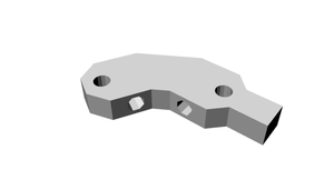
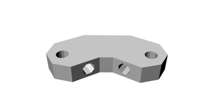
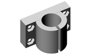
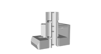
Step 4 Z axis mounts
Components
- 2x Z motor mounts
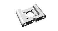
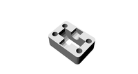
- 2x Rod clamps
- 2x Bar clamps
- 4x M3 20mm screw
- 4x M3 nut
- 4x M3 washer


Instructions
Insert a M3 nut in to each of the nut sized holes on the inside of the two Z motor mounts.

Attach a rod clamp to each of the Z motor mounts using two M3 20mm screws each with a washer.


Attach each a Z motor mount to either side of the upper 440mm threaded rods and attach in place with a M8 washer and M8 nut.


Keeping the frame so that the Y motor mount is facing you, add a M8 nut and M8 washer to the right side of the lower 440mm threaded bar, attach to this a bar clamp, and attach in place with a M8 washer and M8 nut. Repeat on the left side.

The inside edge of the bar clamp on the right side needs to be 72mm from the out side of the nearest bar clamp.

The inside edge of the bar clamp on the left side needs to be 61mm from the out side of the nearest bar clamp.

Y axis assembly
Y axis plate
Components
- 4x LM8UU holder
- 2x Belt clamps
- 4x LM8UU liner bearing
- 20x M3 nut
- 20x M3 washer
- 20x M3 16mm screw
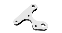
- 1x Y axis aluminium plate
- 2x 406mm stainless steel smooth rod


Instructions
Preparing the LM8UU holders.
Firstly due the way the LM8UU holders are printed they do not rest perfectly flat. Use a knife in a safe manor to scrape the middle of the bottom side until it will sit on a flat surface without rocking.

Use the supplied super glue to glue in place the LM8UU liner bearings, it only requires a small amount to hold the bearings in place. Apply the glue to the plastic part not the metal bearing. Twist the bearing as you push it in to spread the glue around. Wipe off any excess glue and allow to dry. Do all eight LM8UU holders at the same time. Be careful with the glue.

Attach each of the four LM8UU holder to the aluminium plate using the M3 16mm screws, the M3 washers go between the screw head and the aluminium plate.


Attach the two belt clamps but do not fully tighten, attach with two M3 16mm screws with M3 washers and M3 nuts, the plastic clamp needs to be on the opposite side to the LM8UU holders.


Take the two 406mm stainless steel round bars and slide them half way through the bar clamps which are either side of the Y motor mount.

Take the Y axis aluminium plate assembly and slide the two 410mm bars
through the LM8UU bearings, continue to slide the rods until they pass through the opposite bar clamps. Space the spare round so that there is an even amount on either side.


Tighten the rod clamps and check the measurements are still correct, between 40mm and 41mm from the inside of the frame vertex to the inside of the rod clamp. Slide the Y assembly back and forth. If you feel any resistance slightly slacken the screws holding the LM8UU holders to the plate and then re-tighten, this ensures that the holders are seated properly.
Y motor installation
Components
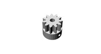
- 1x Pulley
- 1x stepper motor (90cm cable)
- 3x M3 10mm screw
- 1x 840mm T5 timing belt
Instructions
Jump forward to the Wiring section to prepare the stepper motor.
Attach the pulley to the shaft of the stepper motor, ensuring the grub screw in the pulley lines up with the flat section on the shaft. Fit the pulley as shown in the photo below.

Attach the stepper motor to the left side of the Y motor mount using three M3 10mm screws.

Slide the Y plate assembly all the way to the Y motor mount, pass the 840mm T5 timing belt underneath the Y plate assembly. Pass the belt over the pulley (make sure the belt teeth face the pulley teeth) pass over the bearing and under the belt clamp. Ensure at least a 1cm passes past the belt clamp. Using a spanner to hold the nut tighten down the belt clamp with the screws.


Repeat the process on the opposite side, the belt need to be tensioned so that there is little to no slack. (a second pair of hands is useful for this)

Hot End Assembly
Components
- 1x brass heater block
- 1x brass nozzle
- 1x PEEK support block
- 1x PTFE insulator
- 1x Thermistor
- 1x Heating resistor
- 1x PTFE tape
- 1x Silicone sealant
Instructions
Take the PTFE insulator and wrap a few turns of the PTFE tape around the threaded section.


Take the brass nozzle and screw on to the PTFE insulator.

Using the Silicone sealant fix the heating resistor in to the smooth board hole in the brass heater block.

Wiring the Hot End
From the spare wire cut from the stepper motors cut four different colours all 75cm in length.
Solder two of the wires to the Thermistor. (NOTE be careful it is easy to snap the legs off the thermistor

Use PTFE tape to insulate each leg. The use more PTFE to bind together each leg.


Wrap a cm sized square of PTFE tape around the top of the thermistor. Fill the hole in the heater block with silicone and wipe off any excess so that just the hole has silicone in it. Push the end of the thermistor into the hole. Cut a piece of Kapton take and tape down the trailing wire at 90 degrees to the hole. Leave to set (NOTE from now on be very care full with the heater block as the thermistor's legs can brake easily, never hang the block by the cable)


Use two bootlace ferrules to attach the remaining two 75cm wire to each leg of the heating resistor., squeeze and twist the ferrules so that the hold the wire to the leg with pilers. Use PTFE tape to insulate the join. (NOTE as with the thermistor wires do not dangle the heating block by the resistor wire)
Extruder Assembly
Components
- 1x Extruder block
- 1x Extruder idler block
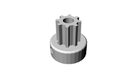
- 1x Drive gear
- 1x Hub gear

- 4x LM8UU holder
- 2x Belt clamp
- 4x LM8UU bearing
- 3x 608zz bearing
- 1x Hobbed bolt
- 1x X axis aluminium plate
- 1x Hot End assembly
- 2x M4 counter sunk 40mm screw
- 2x M4 16mm bolt
- 2x M4 nut
- 4x M4 nyloc nut
- 4x M4 50mm bolt
- 3x M3 8mm screw
- 4x M3 16mm screw
- 4x M3 nut
- 3x M8 washer
- 1x M8 nyloc nut
- 1x M8 nut


Instructions
Take the two M4 counter sunk 40mm screws and attach to the X axis plate through the countersunk holes , fix in place with a M4 nyloc nut on the underside.


Attach the LM8UU holders using the M3 12mm countersunk screws and M3 nuts.


Push two 608zz bearings in the holes on the Extruder block. (NOTE this can be a tight fit, gently squeezing in a vice can help ensure the 608zz bearings are seated correctly)

Use the two M4 16mm bolts to attach the extruder block to the X axis plate use two M4 nyloc nuts to secure in place.


Attach the Drive gear to the extruder stepper motor ensuring the grub screw line up with the flat section of the stepper motor shaft. Fit as shown in photo below.

Attach the four M4 50mm bolts through the bolt shaped holes on the extruder block. Hot End assembly

Take the hobbed bolt and attach the Hub gear to it. Add two M8 washers.

Attach the hobbed bolt assembly to the extruder block, attaching to the side of the extruder block with the motor mount.

Take the extruder stepper motor and hold in place so that the gears engage with each other. You will note that two of the stepper mounting holes are covered by the Hub gear, use one M3 8mm screw to hold the stepper motor in place. Remove the drive gear from the motor shaft, and then remove the hobbed bolt assembly. Attach the stepper motor in place with the remaining two M3 8mm screws which holes are now no longer covered.


Re attach the hobbed bolt assembly, fix in place with one M8 washer, one M8 nut and one M8 nyloc nut.


Re attach the drive gear to the stepper motor shaft, ensuring the grub screw lines up with the flat section of the motor shaft.

Attach the two belt clamps using four M3 16mm screws and four M3 nuts, do not fully tighten yet.


Insert a 608zz bearing and attach the Extruder idler holder to the extruder block to hold it in place.

Add a spring to each of the bolts followed by a M4 wing nut. Do not over tighten.


Attaching the Hot End to the Extruder
Take the assembled Brass nozzle and PTFE insulator and push in the hole in the underside of the extruder.

Add the PEEK support block, making sure it seats on the rim of the brass nozzle correctly.


Use two M4 nuts to hold in place. Tighten until the ends of the bolts are in line with the beginning of the threaded section of the brass nozzle. (NOTE any further and the brass nozzle block will make contact with the bolts)

Z axis installation
Components
- 2x coupleing set
- 2x Y axis steppers
- 2x clear plastic tube
- 8x M3 10mm screw
- 8x M3 20mm screw
- 16x M3 washer
- 8x M3 nut
- 4x M8 nut
- 2x 210mm threaded rod
- 2x 350mm stainless steel round bar

Instructions
Take the clear plastic tubing and cut into two equal pieces. Holding this with pliers gently warm them with a hair dryer, once warm slide down the shaft of the two Z axis steppers.

Temporarily remove the Z motor mounts from the top of each side of the frame, place these upside down on the Z axis steppers, attach to the steppers with M3 10mm screws and M3 washers. Re attach the Z motor mount assemblies to the frame.


Take the two different sides of the couplers and assemble the with M3 20mm screws, M3 washers and M3nuts, test assemble and screw all the way together so that the M3 nuts become fully trapped in the nut shaped holes. Then disassemble. Take the 210mm lengths of threaded rod and trap this inside the coupling as shown in the photo. Tighten just enough so that the rod is held in place. Add a M8 nut as shown in the photo.


X axis assembly
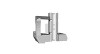
X axis Idler assembly
Components
- 1x LM8UU X-end idler
- 1x LM8UU X-end motor
- 4x LM8UU liner bearings
- 4x cable ties
- 1x 624zz bearing
- 1x 609zz bearing
- 1x M8 mudguard washer
- 2x M8 nut
- 3x M8 washer
- 1x


50mm M8 threaded rod
- 1x M3 16mm bolt
- 1x M3 Nyloc nut
- 3x M3 washer
Instructions
Take the four LM8UU bearings and push them in to the X-end idler and X-end motor plastic parts.

When snapping in the LM8UU bearings occasionally the plastic part around the base can crack, however this is easily fixable with the supplied super glue and does not effect the operation of the part.


Use the supplied cable ties to fix in place.


The X-end idler bracket may need a 4mm hole drilling in for attaching the 624zz bearing, this hole was added after some machines shipped.
Looking at the piece as orientated in the photo measure up from the bottom 19mm and then in 5mm this will give you the centre of the 4mm hole, drill this slowly.


Place the M4 16mm bolt through the hole. Add two M4 washer followed by the 624zz bearing followed by a M4 washer and secure in place with a M4 nyloc nut.


Attach the M8 50mm threaded length of rod through the large hole attach to the inside with a M8 washer and M8 nut.

On the out side add a M8 washer followed by a 609zz bearing followed by a M8 washer, M8 mudgaurd washer, held in place with a M8 nut. On the out side add a M8 washer followed by a 609zz bearing followed by a M8 washer, M8 mudgaurd washer, held in place with a M8 nut.

X axis sub assembly
Components
- 1x X-end Idler assembly
- 1x X-end motor
- 1x Stepper
- 2x 410mm stainless steel round bar
- 3x M3 10mm screws
- 1x Pulley
- 1x 900mm T5 timing belt
- 2x M8 nut

Instructions
Stand the Extruder assembly in the role Kapton tape as shown in the photo so that the large gear is facing you.

Attach the two 410mm smooth rods through the LM8UU bearings.

Slacken off the screws holding the LM8UU holders then re tighten this makes sure they are correctly aligned on the rods.
Attach the X-end idler assembly to the left end of the rods ensuring they slide all the way to the end.

Attach the X-end motor holder to the right side.

Stand this hole assembly on the middle of the Y-axis plate as shown in the photo.

Attach the other end of the coupler to the Z motor shaft, making sure the other end of the threaded rod has located through the X ends. Do this to both sides.

Take the 350mm stainless steel slide down through the rod clamp in the Z motor mount, through the LM8UU bearings in the X ends and down to the rod clamp. Do this on both sides.

Add a nut to the bottom of the 210mm lengths of threaded rod thread up until this sits in side the nut shaped gap on the bottom of the X end idler and the X end motor side. You can now remove the role of Kapton tape.


Attach a belt pulley to the motor shaft as shown in the photo below and attach the to the X end motor holder, with three M3 10mm screws.

With the geared side of the extruder now facing you slide the extruder to the same side as the idler X end. Attach the 900mm length of T5 belting to the left side belt clamp on the X chassis plate. Remove the M8 nut and mudguard washer from the X end idler so that you can pass the belt over the 624zz bearing and under the 609zz bearing, and then reattach the mudguard washer and M8 nut. Tighten down the belt holder with a screw driver while holder the nut still with a spanner.


Feed the belt over the pulley on the motor shaft and attach to the x chassis with the right side belt clamp, the belt needs to be reasonably tight. NOTE there will be excess belt that will need to be trimmed.


Heated print bed
Components
- 1x heated bed plate
- 4x heat resistors
- 1x choc block
- 8x M3 nut
- 8x M3 12mm counter sunk screw
- 2x M3 16mm counter sunk screw
Instructions
Apply a small amount of the heat sink compound to the bottom of the heat resistors and attach to the heat bed using the M3 12mm counter sunk screws, and M3 nuts.


Attach the choc block connector to the heat bed using the two M3 16mm counter sunk screws, the holes in the choc block are tight but the screws do screw in to them. Do not screw all the way so that the choc block is suspended away form the heat bed as shown in the photo below.


Heated Bed wiring
Use the supplied 16 AWG wire to connect each of the resistors as shown in the photo.

Wrap each solder joint with PTFE tape.

Heat bed installation
Components
- 4x M4 40mm countersunk screws
- 4x M4 Nyloc nut
- 8x M4 nut
Instructions
Pass a M4 40mm countersunk screw through the countersunk hole in the print bed and a fix in place with a M4 nut tightly.


Add a second M4 nut to each of the screws, thread it down around a cm of the screw.

Rotate the bed so that the choc block is facing the side away from the Y motor, align the screws with the holes on the Y chassis. Attach with a M4 Nyloc on the bottom of each of the screws. The M4 Nylocs need to be flush with the bottom of the screw, then adjust the middle M4 nut so that it is tight against the Y chassis.


Assuming your build surface is level, use a small spirit level to check the frame is sitting level the best place to check is the top two 440mm threaded rods, or the Z axis motors. If your build surface is not level use paper shims under the frame feet to level the frame. Once the frame is sitting level check the print bed is level. Left to right and front to back. If it is not level adjust the nuts either side of the Y chassis plate.
Wiring
Stepper motor preparation
The steppers are supplied with much more wire that required. You well need to cut the stepper wires to the required lengths below.
Y axis stepper 90cm X axis stepper 45cm Z axis steppers 25cm Extruder stepper 55cm
Next the steppers need their Molex connectors attaching.
Start by attaching the crimps to the ends of the wire. There is a great video here explaining how to do this.
Next gently push the crimps in the connector housing.
With the connector orientated the same way as in the photo the order is
RED BLUE GREEN BLACK

Commissioning
Coming soon.