General
This page and its peers should guide you through assembling a RepRap Huxley from the TechZone kit, or from parts you have printed which are the same as the TechZone parts. It is a work in progress, and needs some help, feel free to edit this document to add comments of you your own, or contact us [here] and send us messages asking us for better clarification or details.
I am starting by posting the pictures I have, and over the next few days, I will fill in the instructions and detials (24 Dec 2010)
Thanks,
Lambert (TechZone R&D/Support/Documenter)
You can access this page and it's peers (for the other parts of the Huxley assembly from the Main Huxley page or from the TechZone Huxley Page
The Z Axis should be put in after the frame and Y axis have been squared, and trued. Information about how to do that can be found here. You should have tightened all nuts and used threadlock on them if you are going to (I recommend that you use threadlock). If you perform the following steps before squaring and trueing up the frame and Y axis, it will be in the way and will make that process more difficult.
Drive Rods
On the left is a picture of the parts used to assemble and prepare the drive rods for the Z axis. On the right is an assembled and prepared Z Drive rod
- (2) 6mm threaded rod (the las 2 in the set) they are about 215mm or 8-1/2" long
- (2) Printed Drive Cogs (shown with nut already installed)
- (2) 626zz bearings
- (10) 6mm nuts
The following are shown in the picture but are not used until the next step (but I mised them in that picture...)
- (6) 3mm X 20mm bolts
- (6) 3mm Nylocs
- (12) 3mm washers --ok... the picture only shows 6...
Begin by putting a 6mm nut into the end of each of the printed cogs. I use a torch to heat the nut slightly (don't overheat it) just like we did for the Z Nut Retainers on the X Axis. I thread the nut onto the end of the threaded rod to heat it (don't burn you fingers!).
Next, assemble the Drive rod with a 6mm nut, the bearing, then three more 6mm nuts, followed by the cog. Place them all on the end of the rod until the rod is flush with the nut in the drive cog as shown on the right.
For now, we remove the drive cog from the drive rod. At this time I rcommend that you put a small amount of threadlock on the top nut and on the bottom nuts. Be careful not to get threadlock into the bearing, since threadlock can ruin the bearing.
Install the X Axis onto the Z drive rods
You will need the Huxley, the assembled X Axis, the two threaded drive rods from above and the printed drive cogs, along with the 3mm bolts, nuts and washers listed in the step above.
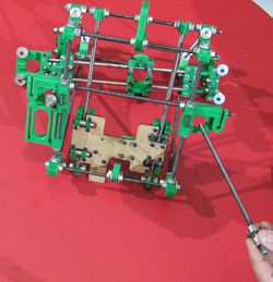
We start by turning the Huxley upside down (or almost upside down) as shown in the picture on the right.
Then Place the X Axis into the space where it will be, put the top of the X Axis towards the top of the Huxley. The smooth side of the X Axis Carriage is the top of the X Axis. You want to put the motor end on the correct side of the machine. I build mine with a backwards X Axis, so that the motors of my Huxley are all clsoe together. I do NOT recommend this for your first machine, since it then requires that you mirror all you parts in order to get them to print corectly. -- I am building a website based toolchain, which will have this ability for you in the near future, but until then it is a fairly advanced thing to mirror the parts for printing; It is just easier to use if you put your X axis motor above your Z Axis driven unit, rahter than above your Z Axis Combo unit.
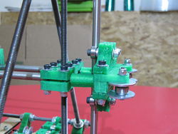
Put the Drive Rods through the Z driven unit, and the Z Combo unit and thread them into the nuts in the Z Nut Retainers on the X Axis, I threat them until they are about two inches I also try to get them nearly even (it makes squaring easier if I get them close now). The picture on the right shows the Drive rod in place on the Combo unit and the drive rod for the driven unit is being put into place.
Align the bearings into the spaces in the Z Combo unit and the Z driven unit. Then use 3 of the 3mm X 20mm bolts on each side with nuts and washers, go ahead and make these fairly snug.
Finally put the drive cogs back onto the end of the rods. Add a drop of threadlock if you wish (I recommend it).
When you are done with this step, your huxley should look something like the top right picture of this section.
Adding the Z Smooth bars
To install the Z smooth bars you will need your Huxley (duh), and the following parts:
- (2) Z Axis Smooth bars (last two in the kit) aproximately 225mm long (8-3/4")
- (4) Z Smooth bar clamps --printed parts
- (10) 6mm nuts
- (10) 6mm washers
- (4) 3mm X 20mm bolts
- (4) 3mm nyloc nuts
- (8) 3mm washers
Start by putting the Z smooth clamps onto each end of the top unit, the printed clamps are bracketed by 6mm nuts and washers, as shown in the picture on thr right. Do this to both ends, leave the nuts loose so we can slide the smooth bar between them.
Slide the Smooth rod into place, it should go between the smooth bar clamps, then through the bearings, and into the bottom clamp. I start with the 360 degree side, then do the 180 degree side. If you need to adjust the X Axis so that the rod can travel a strait path, then look at the next step (Aligning the Z Axis), there is some information about the adjustments to make. Don't force your bars, they should be snug, but you should be able to get them to go into place without breaking things.
Once both bars are in place, you can use the 3mm X 20mm bolts, with washers and nuts, to secure the top of the smooth bar. You can also use two 6mm nuts with 6mm washers to secure the bottom. Don't over tighten the bottom, or you may break your plastic. Things should be quite snug, but this isn't a diesel truck, so take it easy on the torque!
Aligning the Z Axis
Aligning the Z axis can be a little tricky, because the assembly of the X axis is affected.
I start by measuring the distance between the Z smooth bars at the bottom. In my case they are 265mm apart (top left photo). I want to adjust the Z smooth bar clamps, until they too are 265 mm apart (Photo on the Right). While making this adjustment, I want the frame vertices to stay centered, so I adjust both ends, carefully to keep them equidistant from the vertices. To make it more complex, you may need to adjust the X Axis, to space it correctly for the Z Smooth bars.
The Z360 end of the X Axis doesn't really adjust much, since the smooth bar and the threaded rod are tied together, but they can still be moved toward or away from the center a little bit. On mine, I had to loosen the Motor end clamp and move it away from the center by 1.5mm, I then slid the Z Nut retainer away from the center by the same amount.
The Z180 end has more adjustment possibilities. I moved the Idler end away from the center on mine by about the same as I did the motor end (I tried to do them the same, so that the clamps had equal bite on the smooth bars). I also adjusted the Z Nut retainer from the Idler end until the Drive rod and the smooth rod looked parallel to each other. I could have measured it to make it exact, but the drive rods are left floating, to allow for some differenced in the bar spacing, as well as slight bows to the rod. Notice in the picture to the right, that there is now some space between the bar spacers and the Z Nut retainer on the Idler end of my X Axis.
When we assembled the X Axis, we did not tighten all the nuts and bolts on it as we built it. Now is a great time to tighten them. With everything in the correct place.
You may find that you need to adjust the tension of the bearings on the Z Axis. You can do this by tightening or loosening the straight bearing on the 360 end - in some cases you may need to install an additional 3mm X 30mm bolt to pull it tighter onto the smooth bar. When I get everything else adjusted just right, I have not had to do this on any of the machines I have built so far (only three of them).
The 180 side also has a pair of holes for an adjustment bolt if needed. So far, I have been able to get my tension about perfect, by tightening the middle vertical bolt on the idler end to cause it to pull the arms together a bit.


