Gen3 DIY PCB Toner Transfer
Release status: experimental

| Description | Gen3 DIY PCBs - Toner Transfer (MTG)
|
| License | |
| Author | |
| Contributors | |
| Based-on | |
| Categories | |
| CAD Models | |
| External Link |
Contents
- 1 Warning
- 2 Notes
- 2.1 Image 1: ATX / ATX2 supply and UM232R footprint boards
- 2.2 Image 2: Motherboard 1.2v
- 2.3 Image 3: Extruder Controller 2.2v
- 2.4 Optoendstops 3.0
- 2.5 StMoDrv 2.3v
- 2.6 StMoDrv 3.0v
- 2.7 StMoDrv 3.3v Makerbot
- 2.8 StMoDrv 3.3v Mendel "pins compatible"
- 2.9 Alternative firmware(s) for EC2.2 board with independent dual temp
- 2.10 Thermocouple AD595 board
- 2.11 Thermistor board
- 2.12 Thermocouple MAX6675 board
- 3 Photos
Warning
Gen3 electronics is now OLD and DEPRECATED and is NOT advisable for new designs.
That said, if you want to make electronics yourself from the bottom up, like many RepRappers do, have a look at Generation 7 Electronics. Gen7 is explicitely designed to be DIYable and easily on par with other modern RepRap electronics.
Notes
Notes:
- these are NOT variations of the original designs, actually are exactly those! - only just pcb layout "tweaked" for toner transfer
- of course all credits and everything goes to the original authors
- all modifications were intended to be minimal (basically just fattening traces a little), to preserve the original components positions, placements, traces etc. For the same reason, i choose (for myself) to have only the traces on the board no other polygons. This way i can see all traces clearly by putting the board into the light (i use a somewhat transparent cald). While it can be said this is not optimal, it also can be said that is a matter of choice - and some images provided are like that as a result.
Instructions: DIY_PCBs_double_sided_toner_transfer
Image 1: ATX / ATX2 supply and UM232R footprint boards


- File download link: Media:mtg_ttd_accesories.zip
- General device description: ATX / ATX2 voltages takeout + UM232R footprint board.
- Significant changes: No prior versions, only made these boards as alternatives. For ATX supply, the board allows access to all voltages without any modifications to the supply. The UM232R i made because it looks better on a proper board.
- Specific comments for DIY: For both boards, make sure you check the real parts (molex and module) fit on normal paper, before anything else. If the parts dont fit, print the file from an image editor program, at 600dpi, on A4 sheet setting in printer driver. Do not print from browser or from default windows image viewer. Instead of soldering the UM232R module, .100 precision female header can be used to make a "socket" - use precision pins: these are the round ones.
Image 2: Motherboard 1.2v


- File download link: thingiverse.com/thing:4673
- General device description: Motherboard 1.2v
- Significant changes: Mb 1.2v: RepRap modifications included (no longer compatible with other makerbot version), as per http://www.reprap.org/wiki/PCB_adaptions_for_Mendel : the bridge near icsp header area, bridge(s) in atx connector area (leading to two traces in bottom layer to be combined on the top area of sd card - looks weird but its ok), tqfp pads are image edited.
- Specific comments for DIY: Additional image as A4 file, 600dpi, for top and bottm: orientation of the board on the file would of been better horizontal, but then wouldnt fit one near the other. Check photo paper shrinkage (on vertical direction) with a real piece of .100" pins along their holes.
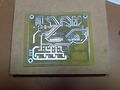
Image 3: Extruder Controller 2.2v
- File download link: thingiverse.com/thing:4673
- General device description: Motherboard 1.2v + Extruder Controller 2.2v
- Significant changes: I did my own EC22 with a version that was almost at the size and spacings of the original file, and after doing it like that i decided it needs further spacing out and more severe cleaning up which i did in the file. As a result the images linked and the file are slightly different, and the last version should be better. However be warned, i did not tried this last version in real life myself, although i think it should work: use at your own risk, etc. Changes: tqfp pads image edited; layout enlarged; severe layout cleanup, many re-tracings; made connection between GNDA (analog gnd) and GND at the left of the crystal on top layer (instead of an alternate layer).
- Specific comments for DIY: Additional image as A4 file, 600dpi, for top and bottm. Slightly complicated board with many vias, so make vias with the reference file on your face to avoid making wrong kind of via connections. Use good quality board and materials. As a sidenote, the brd file has the pin N#20 (Aref) placed a tie to 5v just before C14 which is not clearly appearing in schematic. This means Aref is tied high, although by default the adc makes use of the internal 5v for comparator. To use Aref high, i guess firmware would need "analogReference(EXTERNAL)" but i havent seen this anywhere. At some point i was confronted with some analogRead() jitter for dual sensor situation, so I concluded for myself that is better to cut Aref off from 5v, which i actually did, because it looked like the correct thing to do. Cutting Aref from 5v didnt made any improvement for the jitter i was getting, and i cant see i noticed any difference anywhere else, but this is why the change its mentioned in firmware configuration.h file that is posted on this page. Also caution: testing the extruder without motor attached, but by turning pot to max resulted immediately on my board in burning the top H-bridge, so in my opinion be carefull about that pot.
Optoendstops 3.0


- File download link: thingiverse.com/thing:4673
- General device description: optoendstops 3.0
- Significant changes: it should be failry easy to fit both smd or through hole components;
- Specific comments for DIY: has 4 pin header versus 3 pin headers on the stepper drivers; can be made single sided with 1 top layer wire bridge (but there is no reason for that);
StMoDrv 2.3v


- File download link: thingiverse.com/thing:3424
- General device description: This is the board layout made by mr. Renoir, documented on Thingiverse http://www.thingiverse.com/thing:3424
- Significant changes: Nothing. It is only mentioned here as a part of this "DIY" collection, i hope original poster wont mind.
- Specific comments for DIY: Refer to the original post on Thingiverse.
StMoDrv 3.0v


- File download link: thingiverse.com/thing:4673 (and there are other peoples versions on thingverse aswell)
- General device description: at the time making this, it is the current version of RepRap Driver
- Significant changes: Nothing significant. Just traces width, etc.
- Specific comments for DIY: Image shows a socket for the plcc, because i intended to test it only. Would be wiser to solder the ic instead. Also: i havent actually got around to made it, so i cant say for sure that it works but i dont see why it shouldnt, as there were no changes that could raise this question. My best dilligence, but use at your own risk / keep that in mind.
StMoDrv 3.3v Makerbot


- File download link: thingiverse.com/thing:4673
- General device description: Version 3.3 of stepper driver, at the time making this page, in development set from makerbot (marked ready for production). It does not have the Optoendstops headers, has a 6 pin idc header and it added an reset line pin in it. Because the future mb will have min/max directly on it, which makes more sense.
- Significant changes: This came as an intermediate step in making the version below. More explanations there. Thought to put the file here for further reference maybe for makerbot diy users to do testing on it or maybe when a new mb will be available.
- Specific comments for DIY: Mostly same as below, read there.
StMoDrv 3.3v Mendel "pins compatible"

- File download link: www.thingiverse.com/thing:4673
- General device description: Same file as above, with 10 pin idc header and min/max headers for compatibility with Mb 1.2v, reset no longer connected to idc header for mb.
- Significant changes: changed smd from 0805 to 1206; increased pcb size and spacings accordingly; some provisions(”just in case”): 7805 can be fitted with a small to radiator and can be moved around abit if needed (also consider using 78L05 instead); smd versions electrolitic capacitors could be fitted (for smd connect the vias nearby with bottom layer); alternative jumpers instead of the dip switch; alternative 0.100” pins connectors for motor; 2 opposite diagonal holes for an eventual A3977 radiator, and some holes underneath A3977 that are just something like chip vent; should be easy to fit pots with 5/5mm pitch (instead of 5/2.5);
- Specific comments for DIY: Made a set of 3 with common supply lines and all seem to worke allright on first try. Because its "tuning" capabilities this 3.3v should be ideal for extruder so a set of 4 from start would make sense. If you plan to use smd versions C10 C11, may consider doing the nearby vias top connections only after populating these condensers. Underneath the a3977 i made some "venting" holes. I only use the traces so the pcb lacks alot of copper surface, as a result i would say serious overkill heatsinking on a3977 is in order (i used approx 40/35mm aluminium radiators). Fattening all traces with additional solder is good, especially on gnd lines - at least the ones entering the chip from top and below. Use of voltage regulator 78L05 (~0.1A) instead the original, is highly recommended! The original 7805 (~1A) could make the board "more likely to fry with a loose motor connection or ESD strike" (quote from a comment in the page linked below). Also recommending a different value for C6: you may want to use 220nF instead of original value in the file 100nF - this might make the board run smoother.
- Usage / tuning for a certain motor: Mr. Nophead did some research on this board see this link http://hydraraptor.blogspot.com/2009/12/motoring-on-with-a3977.html (and linked pages). Also recommending lectures of 1)datasheet and 2)applications note sheet (link from allegro site FAQ of a3977) - this application note feels more like a "product family" documentation so maybe datasheet values should have priority over it.
Quick references (use at your own risk!):
Vref: This sets the max current with Itrip(max)=Vref/8*Rs and Rs are the 0.25 resistors, so half this value gives the current set. A place to start can be a low value like 1.2V (thus ~0.6A) and only if needed, slightly increase until motor gets the desired torque, but without overshooting the motor rated Amps. Normally about 1.2-1.5V may be quite enough for reprap. Vref can be max 4,0V when microstepping ! and can get =vdd only if full stepping is used. Anyway considering that the motors heat up alot and are positioned in plastic brackets, they could be under-run at some margin, to get their temperature lower. The objective is to have the motor current (thus operating temperature) as low as possible while device still works properly, giving the needed torque without missing steps.
RC1 & 2: Values are adjusted in ohms not voltage, and should be identical at all times rc1=rc2. Can be measured offline. The rc values may need some "motor math" to discover proper values, see links above. Frankly I am missing a clear way to determine the proper value for different motors. I suspect a value from 30k - 56k would be a good place to start in some cases (motors with relatively acceptable low coil resistance - but not extremes), but ofc this cant hold true for all motors, so take the precautions needed in this area and review the proper documentation for it. The CT value on this board is 470pf (C13 and C14), although the a3977 datasheet considers CT 680pf and RT 56k at some point (also 1000pf is more common CT value on various similar a3977 boards i have seen on the net). These different CT values might be tested as replacements. Some caps, depending on dielectric will loose more or less of their capacitance. Probably best here to use C0G-NP0 dielectrics, with second and last choice X7R. Others dielectrics may do bad under the conditions, and loosing some of their capacitance may alter the entire CT-RT math. More documentation here, especially on CT-RT theory and math would be highly appreciated.
Vpfd: (voltage percent fast decay)- its voltage changes the decay mode e.g. 0~1.05V the decay is fast, and over ~3V its slow decay, while in between these values its a mixed decay mode with more fast or more slow depending on which value the setting is closer to (how much slow and how much fast is a formula on app note sheet). Generally speaking fast decay ... is fast, but also gets more ripple and increases the heating, so bottom line: chances are the motor will not behave nicely with 100% fast decay, and if thats the case try going up, to mix mode decay, first in lower half of its interval, where fast portion is still predominant, e.g. between 1.05-2V and see if things improve. There is a video on adjusting the pfd in the pages from the link mentioned above.
Alternative firmware(s) for EC2.2 board with independent dual temp

Old FiveD
- File download link (old FiveD firmware, very old and very obsolete now, do NOT use): Media:mtg_SuperSimple_v1b.zip
- General device description: Alternative firmware for EC2.2 - tweaked for independent dual sensor (Extruder_simpler folder). Also some firmware for MB1.2 is also included for compatibility, and some more complete code for extruder although these suffered (almost) no change and i had (almost) nothing to do with them, but might just come in handy for someone at somepoint.
- Significant changes: This is a rip from the official firmware, the following have been taken out: -pid control -A3949 hack -paste extruder. For a change this has simple bang bang control, and it can read and actually control the heated bed too. I made the measuring methods independent: e.g. measuring extruder with a thermocouple of choice and heated bed with the thermistor - something the "official" firmware still cannot do (at least not when this was posted - keep checking current status).
- Specific comments for DIY: Heated bed "should" use a different power source, but still can be controlled by EC, probably with some optocoupler. Note that the legend on the EC2.2 may be wrong about A6 and A7 pins. Looking at board oriented with the crystal at bottom and A6 A7 connectors above it, the correct pinout from top to bottom is Gnd-5V-A6 and Gnd-5V-A7. I tested the combinations of thermistor and ad595, but i dont have a max6675 chip so that part still needs to be tested.
- Very few comm debug tips: Try baud rate 9600 on host port + firmware see if it seems better. Some reported that 57600 may be better. Further on, FTDI port settings on pc beyond obvious baud rate etc - advanced tab could use "serial printer" checked and maybe 16ms++. Usb devices power "always on" and "dont inform me of usb errors" (or smth like that), etc. The RS485 comm settings are in intercom.h for both boards, check they are the same.
Note: this firmware is kind of outdated, try newer firmwares for a change. This one was for the purpose of different type sensors on EC22. On the big picture from my personal experience and opinion, i would rather recommend Teacup firmware which seems to work nice with classic Gen3.
Teacup
- File download link (Old Teacup version (complete) including settings for Gen3, it compiles with Arduino0022): Media:mtg_Teacup_Firmware_old_config_gen_3.zip
- Comments: Its an older version of Teacup that i got working on my Gen3. Includes gen3 config files.
- Instructions: Install older arduino 0022 version separately from the current version that you are using. With 0022 version open the *.pde, hit compile and upload, both on mb12 and ec22 (these files wont compile with Arduino 1.x, due to version changes).
- Specifics: These files contain 2 temps & heaters: extruder and bed, and have thermistor table file reflect 2 thermistors. Note first part of extruder thermistor table is customized/corrected by for my own thermistor. You should correct your temperature values like that on your own, to confirm they reflect real temperatures. It is done by using a multimeter with thermocouple inside heater barrel, set a temperature in the table right side, read real temperature achieved, and correct it inside the table right column (in case of teacup the right side column is made of temperatures * 4). If you dont want the heated bed, you need to comment it out and also change the thermistor table accordingly to only 1 thermistor table. Also should double-check the pins definitions, especially the heaters. Just in case you want to update to a newer version, dont overwrite newer config files with these older config files. Only use these as informative source on the relevant settings for temperature settings over TT_INTERCOM (with extruder controller attached).
Convert Gen3 to single uC system
Further alternatives: To read temperature besides the thermistor, you can just use 1 cap + 1 resistor. To control a fet, you only need to tie 1 pin from motherboard uC to the gate pin of a logic level power mosfet (and rest the fet source pin to the power source gnd and fet drain pin to the ground of controlled device). Easy to see that as an alternative idea, with 1 resistor and 1 capacitor each, we can improvise 2 temperature sensors directly on Motherboard 1.2, on the breadboard pins, and from same breadboard area we can take out 2 wires to the gates of 2 power mosfets in the usual reprap circuit (just dont use the board ground for the mosfets high current paths, instead just have proper hefty wiring directly from psu and to the device controlled: bed/extruder). With such prequisites we can drop off the Extruder Controller 2.2 board completely, to get single processor setup for reprap. This allows support of virtually all firmwares around, with proper customized configuration.
A long time ago, Extruder Controller board was more of a servo controller for the DC motor driving extruder, not really needed just as an temperature reading board: motherboard 1.2 can pretty much do that job too.
Thermocouple AD595 board

- File download link: Media:Mtg_tt_Tad595_211.zip
- General device description: Based on Thermocouple Sensor 2.1 (from svn). It uses ad595 ic which translates the output of a thermocouple wire into linear voltage (10mV/C), voltage which is then sent to one analogue pin on extruder controller to be read and translated into temperature. The board has an alarm circuit and an rc filter. It can be used as the primary temperature sensor (for extruder) while the thermistor output on EC22 (pin3) can be used for heated bed reading. The advantage of this thermocouple ic is that it uses only 1 analog input of the mcu. A disadvantage is that its seems pretty sensitive to noise. Maybe a current mode transmission could solve this (AN369). In dual sensor configuration the EC22 mcu seems to increase the instability (presumably by internal noise) and a "so-so" workaround is to use in firmware 3 fake analogRead() of the pin, before the actual read that will be converted. Bottom line (for me at least), dual temp with thermistors seems to be more stable and robust than with ad595 - sadly.
- Significant changes: None. Connector pins. Only added compensation caps on top layer, but shouldnt be needed at all, these are sort of provisional.
- Specific comments for DIY: Pictures to the right are not be the exact last variant. When trying to mount it, i wanted some free board space to have some hole space variants. Board can be normally made one sided. Optionals are the entire top layer, and ultimately all components: alarm circuit, rc filter, and compensation caps. But it just looks better with those. The compensation caps can be left out (doesnt seem to be really needed and use those if you know what you are doing). The datasheet says that soldering the ic directly is better for noise purposes, and it makes sense, but i made one soldered and 2 socketed and i cant notice any difference, so i would recommend socketing the ic, it doesnt seem to be all that critical. For testing purposes, shorten the thermocouple outputs together and the ad595 will just read the room temperature (and temps up to 150C). This may also be useful when trying to isolate eventual sources of noise. Maybe 90 degrees .100 pins would fit directly on A6-A7 connectors. Extra care on connector pinout: Gnd-5v-Sig.
Thermistor board

- File download link: Media:mtg_tt_Ttherm_20.zip
- General device description: Its the Temperature_Sensor_2_0. This incorporates the required components to add a second thermistor to EC 2.2. So the heated bed can be measured with one thermistor and the extruder with the other.
- Significant changes: None. Connector pins. Single sided. This is just for the purpose to get the toner transfer images.
- Specific comments for DIY: R3 is 1k just for the led, and in using R1 and R2 there is some liberty. Either have r1=680 and r2=1k6 or use r1=0 and r2=4k7 as in EC2.2 and usual reprap. Either way, when using the python code to make the table, the correct r1 and r2 should be entered, and consider the adc difference between the cases. Some .100 pins would fit directly on A6-A7 connectors and ultimatelly with just a cap and r2 can be soldered directly on top of pins - no pcb needed. Extra care on connector pinout: Gnd-5v-Sig.
Thermocouple MAX6675 board

- File download link: Media:mtg_tt_Tmax6675_10.zip
- General device description: I guess this is how max6675 thermocouple board would look like. And i really mean "i guess" - as i dont have the ic to test. Max6675 is a little different, it uses SPI to talk to mcu thus it needs more pins than ad595, but in exchange it has its own built-in adc.
- Significant changes: None. Pulled from the depths of the svn. Added a cap and a resistor - hopefully in the right places.
- Specific comments for DIY: Single sided. The JP is for the flying lead noted with "sig" (just as a manner of notation compatible with the other thermocouple and thermistor boards). If any1 can test it, and this board has issues, or any tips to improve it - say something.
Photos
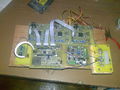
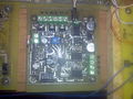
electronics -oe
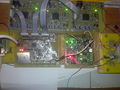
electronics -oe, all tests ok
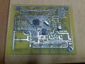
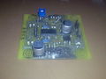
MB 1.2 in works top
MB 1.2 in works bottom
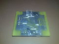
EC 2.2
StMoDrv 2.3v [made by Renoir]
StMoDrv 2.3v [made by Renoir]
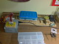
Horizontal sliding etching tank made from a garbage printer's carriage


