FoldaRap1 Build Manual/fr
|
English • العربية • български • català • čeština • Deutsch • Ελληνικά • español • فارسی • français • hrvatski • magyar • italiano • română • 日本語 • 한국어 • lietuvių • Nederlands • norsk • polski • português • русский • Türkçe • українська • 中文(中国大陆) • 中文(台灣) • עברית • azərbaycanca • |

Cette page doit être mise à jour pour refléter les dernier changements de la version en anglais, en attendant il est préférable de s'y référer ou de comparer avec celle-ci
Outils nécessaires
- Clés hexagonales
- 1,5 mm (pour les vis sans tête des poulies)
- 2 mm (pour les vis à tête fraisé M3 et les coupleur pneumatique "MA-12-03-M5")
- 2,5 mm (pour les vis M3 et les M4 à tête bombée)
- Un petit tournevis plat (1,5mm) (pour les borniers de la carte électronique)
- Un tournevis cruciforme (Philips PH2) ou un plat (3mm) (pour les bornier de l'alimentation)
Vous aurez peut-être également besoin de :
- une petite pince et une large (pour serrer la buse à chaud ou tenir un écrou)
- quelque chose pour couper et dénuder des câbles (couteau, pince automatique, etc.)
- un fer à souder (pour les câbles, les cosses, et les borniers de la carte).
- un briquet (pour les gaines thermorétractables)
- des petites limes (plate, ronde) pour éventuellement nettoyer les pièces imprimées
- un pistolet à colle (il est plus simple/rapide de coller les interrupteur de fin de course que de les visser)
Vue d'ensemble En cas de doute n'hésitez pas à jeter un oeil au modèle 3D dans Sketchup (avant/pendant la construction). Cela vous montrera l'état plié/déplié de la machine et vous permettra de tourner autour et voir comment les pièces s’agencent entre elles :)
Basiquement nous avons une structure principale et plusieurs sous-ensembles, la plupart de ces derniers peuvent être réalisés à n'importe-quel moment ou en parallèle, autrement dit : réunissez des amis pour aller plus vite voir battre un record d'assemblage ^^
Voici un essai de diagram de Gantt pour expliquer ça :

Astuces générales :
- Prenez le temps de vous familiariser avec chaque pièces et composants, ne vous jetez pas sur le montage tête baissée ou sans avoir lu une première fois l'ensemble des instructions.
- Travailler sur une planche à découper peut être pratique, pour protéger la table ou vérifier rapidement la taille des vis grâce à la grille millimétrée (même si avec l'expérience vous saurez les reconnaître à vue ou juste en les tenant).
- Durant les étapes de montage, laisser votre souris au-dessus d'une image si vous vous demandez de quelle pièce il s'agit.
- Comment insérer un écrout en T :
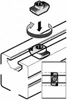 Torque de serrage : 2.5 Nm (+/- 5%) (en gros pas besoin de forcer)

<videoflash>9CAiVmfO2mk|320|240</videoflash>
Ok, commençons !
La construction devrait prendre entre 4 et 20 heures, selon votre expérience et si certains sous-ensembles ont déjà été préparé.
Contents
- 1 Z-axis
- 2 Rear Base
- 3 Front Base
- 4 Bed-plate
- 5 Y-carriage
- 6 X-motor
- 7 Extruder
- 8 Hotend and thermistor
- 9 Power Supply
- 10 Great ! You are almost done !
- 11 Wiring
- 12 Y-axis (105mm between smooth rods)
- 13 X-axis (30mm between smooth rods)
- 14 Top Frame
- 15 Setting the Z-sliders (242mm between threaded rods)
- 16 Tidying
- 17 Leveling the bed and zeroing
- 18 Go go go first print !!!
Z-axis
Les profilés en aluminium ne sont pas tous égaux ! Au moment d’enchâsser une pièce sur un profilé vous constaterez que selon le coin choisi, certains glissent mieux que d'autres.
Il est important pour les pièces X-motor et X-idler (qui vont glisser en Z) de leur trouver un coin qui marche bien sur un des grand profilés. Notez-le et veillez à préparer les poteaux gauche et droite sans perdre de vue l'orientation de ce coin.


Right
 x1
x1
 x1
x1
 x1
x1
 x1
x1
 x2
x2
 x2
x2
 x3
x3
 x1
x1
 x1
x1
- moteur nema14 Z right (dont le câble sera raccourcis à environ 17cm)
- vinyl coupling (glissé à moitié sur l'axe du moteur)
<videoflash>xxfFqePB1qk|320|240</videoflash>
Left
 x1
x1
 x1
x1
 x1
x1
x1
x2
x2
x3
x1
x1
- moteur nema14 Z left (dont le câble sera raccourcis à environ 25cm)
- vinyl coupling (glissé à moitié sur l'axe du moteur)
- z-endstop (25cm blue wires) + m3x8 (or use a glue gun, that's also a very good solution)
<videoflash>E0LTPixdv0M|320|240</videoflash>
Rear Base


 x1
x1
 x1
x1
 x2
x4
x2
x4
x8
x8
<videoflash>R-FKKoWC1hw|320|240</videoflash>
Front Base


 x1
x1
 x1
x2
x1
x2
x8
x8
- y-endstop (32cm green wire) + m3x12 + m3 nut (or glue gun)
<videoflash>zFjVM068mtI|320|240</videoflash>
- y-idler
x2
x2
x1
 x2
x2
- 623zz bearing
<videoflash>VHMia_wi4TQ|320|240</videoflash>
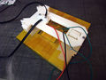
Bed-plate
 x4
x4
x4
x4
(m3x10 is fine, but the m3x12 allow you to eventually add a sheet of insulation)
- Plug the peltier in an adequate power supply (e.g : 12v) to check which side is heating. Don't worry if you put it wrong, you can always switch the cold/hot side by inverting the +/- wires on the board at any moment.
- alu plate
- wood
- peltier (thermal grease)
- thermistor (26awg blue 30-35cm, ferules, kapton)
- kapton
<videoflash>cq9UrSuX4wo|320|240</videoflash>


Y-carriage
 x3
x8
x6
x3
x8
x6
 x2
x2
 x3
x3

- bed springs x3
- zip-tie x3
- 600mm belt
- lm6uu or rjmp-01-06 x3
+Bed
Tips : if the bearing mount are too loose, you can add a little drop of glue or a very small amount of blue tack in the bearing grooves.
<videoflash>m6JDE4KDay4|320|240</videoflash>
- Clamp the belt in the middle of it's length
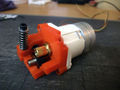
X-motor
 x1
x1
- oil
 x3
x3
- x-endstop (50cm red wire) + m3x8 (or glue gun)
- nema14 X (50cm)
- pulley
<videoflash>ffVmqxLEW58|320|240</videoflash>
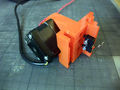
Extruder
x2
x3
x1-3
 x1
x1
If your motor came with an aluminium gear, here is how I remove them (M4 bolt+hammer+vice) : <videoflash>pT2zk--KqBo|320|240</videoflash>


- 623zz + m3x20 (or a rubber roller with oil)
- gros ressort
- m3x35
- moteur d'entrainement du fil de plastique (dont le câble sera raccourcis à environ 50cm)
<videoflash>Qw6U9_q8BCo|320|240</videoflash>
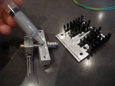
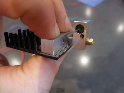
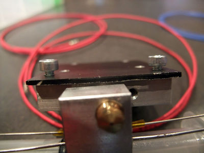
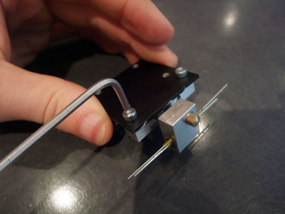
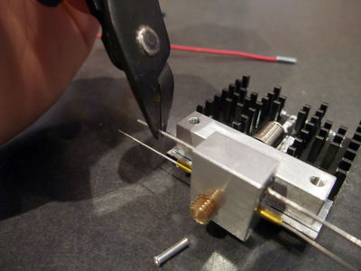
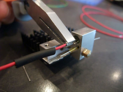
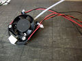
Hotend and thermistor

- resistor 60cm 22awg wire
- thermistor 60cm 26awg (or leftover from the motors)
- fan prolongated to match 60cm
<videoflash>tW_CswHS2OM|320|240</videoflash>
This video is the first I made of these series, and is far from perfect (bowden tube goes before the heatsink!). I'll remake it later but for the moment it's better than nothing (and there is always a good doc on the RepRapPro_Huxley_hot_end_assembly)
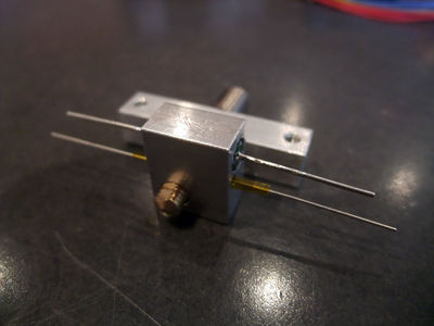
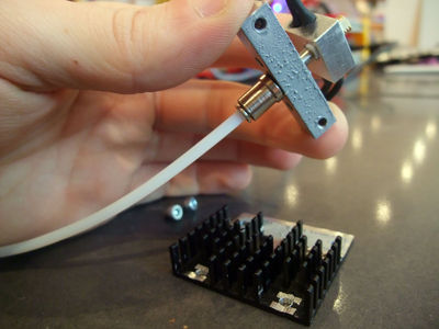
don't forget to put the ptfe tube in the pneumatic fitting, before adding the heatsink (the tube will fit snuggly between the fins)


Power Supply
x4
x4
- power supply
- acrylic plate
<videoflash>_tXWGjJq0zM|320|240</videoflash>
- Bolt the PSU on the plate, with a washer between the psu and the plate
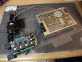
Board
x1-2

- Refer to Azteeg_X1
- board
- stepper drivers
It is maybe a good time to check if the stepper drivers are correctly set (see Pololu_stepper_driver_board and SureStep82 user guide) (Vref = 0.4 for the nema14, 0.32 for the PG35L)
You don't need to plug the power supply for that, if you have set the jumper to "usb" instead of "int", the USB connection is enough for this checking phase.
- board to power supply : 8cm red/black wires
<videoflash>o5W4oZXCXOw|320|240</videoflash>
Y-motor
 x7
x5
x2
x7
x5
x2


- nema 14 Y (15cm wires)
- pulley
- male plug
- big blue switch
- heatshrink sleeve
- Power supply to male plug : 1 green wire of 35cm 18AWG, one end with ferule, the other end just stripped
- Switch to power supply : 1 red and 1 black wire of 34-35cm 18AWG, one end with ferule, the other end just stripped
- Switch to male plug : 1 red wire of 6cm, 1 black of 9cm 18AWG, both ends with ferule
<videoflash>BiiBkZKw1og|320|240</videoflash>
Great ! You are almost done !
Have a pause, you need to be relaxed for the next step, or you can also just head to the end :)
Wiring
At this stage you should have all of these sub-assembly :
the frame
y-carriage and bed
x-motor and endstop
the extruder and it's idler
the hotend, assembled but nozzle not yet tightened
the underplate and a beginning of the wiring phase


Now lets plug everything to the board !

- 18 AWG : power
- 22 AWG : heat
- 26 AWG : sensors (you may use the leftover from the motors)
- Nema 14 sequence : red, blue, green, black
- For the geared stepper PG35L, after trying the three sequence (as suggested by StepperMotor#Shortcut_for_finding_the_proper_wiring_sequence), I found the order : Black (1B), Green (1A), Orange (2A), Yellow (2B)
- Y-motor (15cm, under the board)
- X-motor (50cm)
- Z-motors (17cm and 25cm)
- Extruder-motor + fan
- Y-endstop (green 32cm)
- Z-endstop (blue 25cm)
- X-endstop (red 50cm)
- Hotend-thermistor (blue 60cm)
- Hotend-resistor (red 60cm)
- Hotend-fan (red/black 60cm)
- Bed-thermistor (blue 30-35cm)
- Bed-peltier
Finish by the bed wires (peltier and thermistor), as they will move they need to be above all the other wires.
<videoflash>|320|240</videoflash>
Y-axis (105mm between smooth rods)
- 300mm smooth-rods x2

make a loop at each end of the belt with zip-ties (the orientation showed is the best I found), trim everything but keep a short length on the tensioning zip-tie to be able to pull on it with a plier.
- Slide the smooth rods through the Y-idler or Y-motor part, put the Y-carriage (aka frog) on the smooth rod and then finish to slide them through the other part. To align the Y-motor and Y-idler check that the carriage run smoothly. Since the Y-motor is already in the middle thanks to the 6mm bump on the rear-foot-left, use the carriage to set the Y-idler's distance from each front-foot (expected to be ~12mm from each inner side), once satisfied you can lock them in place with their respective round M4x8.
- Tighten the belt by closing the loop with zip-ties.
<videoflash>|320|240</videoflash>
X-axis (30mm between smooth rods)
X-ends
 X-motor sub-assembly
 x1
x2-4
x1
x1
x2-4
x1
- oil
- 623zz
<videoflash>|320|240</videoflash>
Extruder

 extruder sub-assembly
+ fan
x1
x1
<videoflash>XdfJH7XhZbk|320|240</videoflash>
X-carriage
x4
x4
- lm6uu or rjmp-01-06 x3
- 300mm smooth-rod x2
- 700mm belt
- zip-tie x2
- hotend
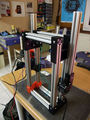
Top Frame
 x1
x1
 x1
x1
x1
x1
 x1
x1
x8
x8
<videoflash>|320|240</videoflash>
Setting the Z-sliders (242mm between threaded rods)
x4
- 230-235mm threaded rod
- turn the rods in the x-ends to push them in the vinyl coupling
<videoflash>|320|240</videoflash>
Tidying
- spiral wrapping band : for the wires that came out of the base (30cm left / 57cm right).
<videoflash>|320|240</videoflash>
Leveling the bed and zeroing
The Z-zero is made when leveling the bed.
- Start by roughly leveling it
- then move the nozzle to the lowest point
- and adjust the 3 screws to level it regarding that height (by turning them until the homing move stop lowering the springs)
- repeat on each corners so the zero is exactly when the nozzle stop touching the bed (true for the four corners+center)
- I like to start with the X direction (from the middle of the two left-screws to the right screw)
- then only working on the left side, trying alternatively from the front to the end corner
- after that it's supposed to be leveled but may need few more tweaking for the right corners
- Skeinforge : you will only have to add a little offset (altitude), to have the desired height for the first layer, usually the same as your layer height.
- Slic3r : leave z-offset at 0, it will add one layer height automatically.
Another advantage of that : by moving to the center of the bed from the zero height, the nozzle is also wiped by the side of the bed from any purged plastic
Faire le Z-zéro en ajustant le niveau du plateau :
- Commencer par à peut prêt le mettre de niveau (i.e. : la tête de chaque vis dépasse de la même hauteur les écrous)
- Descendre ensuite la buse au point le plus bas du plateau, ça sera notre hauteur de référence.
- Ajuster les 3 vis pour mettre à niveau le plateau à cette hauteur (en les serrant jusqu'à ce qu'un mouvement "home-Z" de la buse n'exerce plus de pression visible sur les ressort).
- Répéter pour chaque coin, ainsi le zéro sera exactement quand la buse arrête de toucher le plateau
- J'aime bien commencer le long de l'axe X, du milieu des deux vis au coté avec une seule vis
- Ensuite en travaillant du coté des deux vis de réglages, pour ajuster en regardant l'avant et l'arrière du plateau
- Après ça le plateau est supposé être à niveau, mais pourra demander encore un tout petit peut de réglage pour les deux autres coins (coté vis seule).
- L'avantage de prendre la buse pour référence plutôt qu'un niveau à bulle c'est qu'on évitera les approximations sol/table/bulle, et la distance entre le plateau et la buse sera constante sur toute la surface.
