PC-Netzteil
|
English • العربية • български • català • čeština • Deutsch • Ελληνικά • español • فارسی • français • hrvatski • magyar • italiano • română • 日本語 • 한국어 • lietuvių • Nederlands • norsk • polski • português • русский • Türkçe • українська • 中文(中国大陆) • 中文(台灣) • עברית • azərbaycanca • |
Contents
Elektroniken, die für PC-Netzteile vorbereitet sind
Einige RepRap-Elektroniken sind geeignet, PC-Netzteile direkt und ohne Modifikation anzuschliessen. Hier steckt man einfach die am Netzteil bereits vorhandenen Stecker in die passenden Buchsen der Elektronik.
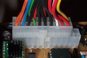
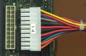
Das Bild zeigt den 20-poligen Stecker eines PC-Netzteils, der in eine 24-polige Buchse gesteckt ist. Jede Kombination von 20- und 24-poligen Steckern und Buchsen ist möglich.
Grundlast
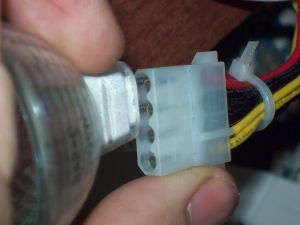
Viele PC-Netzteile (nicht alle) brauchen eine Grundlast auf dem 5 V-Anschluss um zu funktionieren. Bewährte Methoden dafür sind, ein altes CD-Laufwerk oder eine 12 V-Glühbirne (an einen 5 V-Pol, siehe Bild) anzustecken.
Ob man eine Grundlast braucht, muss man ausprobieren. Geht das Netzteil bei der kleinsten Belastung auf 12 V aus, braucht man sie. Schaden tut eine Grundlast in keinem Fall.
Liste der vorbereiteten Elektroniken
Minimalanforderungen
Die Minimalanforderungen sind ein wenig trickreich, denn einige Netzteile mit sonst gleichen Spezifikationen funktionieren besser als Andere. Offensichtlich vertragen sich die Spannungsregler innerhalb des Netzteils mal mehr, mal weniger mit temperaturgeregelten beheizten Tischen. Bei der Temperaturregelung wird der Tisch sehr schnell ein- und ausgeschaltet, das ist auch unter dem Namen Pulsweitenmodulation (pulse width modulation, PWM) bekannt.
Im RepRap-Forum gibt es eine Reihe Erfahrungsberichte mit Netzteilen (englisch). Der 5V-Anschluss ist immer überdimensioniert (was nicht stört), die Aufmerksamkeit sollte auf dem 12V-Anschluss liegen.
Modifikation eines PC-Netzteils für allgemeine (RepRap)- Verwendung
Anschluss des Netzteils
Es gibt drei Arten von PC-Netzteilen, denen Du begegnen kannst. Für alle werden hier Hinweise zur Verwendung gegeben.
Im Allgemeinen brauchst Du nur eine schwarze Leitung (Masse) und eine gelbe Leitung (+12V) an den RepRap anzuschließen. Um höhere Ströme liefern zu können, ist es eine gute Idee, mehrere von den schwarzen Leitungen zusammen anzuschließen, um die Masse zu liefern, und mehrere von den gelben Leitungen zusammen anzuschließen, um die +12V zu liefern. Überprüfe anhand des Typenetiketts am Netzteil, wie viel Strom es an den 12 Volt liefern kann. Bei einem modernen Netzteil werden das gewöhnlich 8 Ampere oder mehr sein. RepRap braucht 5 Ampere, verwende also kein Netzteil, das nur für weniger Strom ausgelegt ist.
Farbcodierung
Die Farbcodierung ist bei all diesen Netzteilen vereinheitlicht:
- Schwarz: Masse (Ground)
- Rot: +5 V
- Gelb: +12 V
- Orange: +3,3 V
- Weiß: -5 V (bei einigen neuen Netzteilen nicht vorhanden)
- Blau: -12 V
- Grau: Einschaltanzeige
- Purpur: Standby-Stromversorgung (für RepRap nicht benötigt)
- Grün: Einschalt-Eingang.
AT-Netzteil
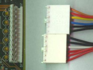
Dies sind die älteren Netzteile. Sie haben zwei 6-polige, verpolungssichere, einreihige Steckverbinder, die nebeneinander auf dem Motherboard eingesteckt werden.
Um diese zu nutzen, müssen keine besonderen Anforderungen erfüllt werden. Sie sind am leichtesten zu verwenden.
"Klassisches" ATX-Netzteil
Diese Netzteile können daran erkannt werden, dass sie einen 20-poligen, zweireihigen, verpolungssicheren Molex-Steckverbinder haben, der auf dem Motherboard eingesteckt wird.
Um diese zu verwenden, musst Du die grüne Leitung des Motherboard-Steckverbinders an eine der schwarzen Leitungen anschließen, damit das Netzteil sich einschaltet, wenn Du es einschaltest. Als Alternative kannst Du einen Schalter zwischen die grünen Leitung und eine schwarze Leitung schalten, dies ist dann Dein Hauptschalter zum Einschalten des RepRaps.
Die 3,3V-Feedback-Leitung muss an +3,3V angeschlossen werden. Dies ist eine braune oder orange Leitung an Pin 11 des Steckverbinders. Er sollte an die 3,3V (orange) angeschlossen werden.
Pinbelegungen
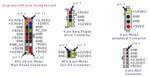
Bei den meisten Steckverbindern stehen die Pin-Nummern oben drauf, aber falls nicht, so liegt bei Draufsicht, wenn die Verpolungssicherung nach unten zeigt, der Pin 1 links oben. Die Nummern zählen dann von links nach rechts an der Oberseite entlang (Pins 1 bis 10) und dann von links nach rechts an der Unterseite entlang (Pins 11 bis 20).
- +3,3V (orange)
- +3,3V (orange)
- Ground GND (schwarz)
- +5Vdc (rot)
- Ground GND (schwarz)
- +5Vdc (rot)
- Ground GND (schwarz)
- PWR-OK (grau)
- +5V VSB Standby-Spannung (purpur). Max. 10mA
  10 +12V (gelb)
  11 +3,3V (orange, braun ist die 3,3Vdc Feedback-Leitung)
  12 -12V (blau)
  13 Ground GND (schwarz)
  14 PS-ON ("Netzteil ein") (grün). Low-aktiver Steuereingang. Mit Ground verbinden, um das Netzteil einzuschalten.
  15 Ground GND (schwarz)
  16 Ground GND (schwarz)
  17 Ground GND (schwarz)
  18 -5V (weiß)
  19 +5V (rot)
  20 +5V (rot)
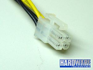
ATX-Netzteile haben normalerweise einen Hochstrom-12V-Ausgang, der an einem verpolungssicheren 2x2 Steckverbinder anliegt. Möglicherweise möchtest Du stattdessen diesen Ausgang verwenden.
ATX-2-Netzteil
Diese Netzteile können daran erkannt werden, dass sie einen 24-poligen, zweireihigen, verpolungssicheren Steckverbinder haben, der auf dem Motherboard eingesteckt wird.
Um diese Netzteile zu verwenden, musst Du die grüne Leitung an die schwarze anschließen (siehe die vorangehenden Hinweise zum ATX-Netzteil).
Außerdem müssen wie beim ATX-Netzteil die Feedback-Leitungen angeschlossen werden. Im Allgemeinen ist eine 3,3V-Leitung vorhanden (orange oder braun an Pin 13), die an 3,3V (orange) angeschlossen werden muss. Bei ATX-2-Netzteilen sind möglicherweise weitere Feedback-Leitungen vorhanden, die an die entsprechenden Spannungen angeschlossen werden müssen. Dies sind normalerweise dünnere Leitungen, und sie sollten an eine Leitung gleicher Farbe angeschlossen werden.
Pinbelegung
- +3,3V (orange)
- +3,3V (orange)
- Ground GND (schwarz)
- +5Vdc (rot)
- Ground GND (schwarz)
- +5Vdc (rot)
- Ground GND (schwarz)
- PWR-OK (grau)
- +5V VSB Standby-Spannung (purpur)
  10 +12V (gelb)
  11 +12V (gelb)
  12 +3,3V (orange, braun ist die 3,3Vdc Feedback-Leitung)
  13 +3,3V
  14 -12V (blau)
  15 Ground GND (schwarz)
  16 PS-ON (grün)
  17 Ground GND (schwarz)
  18 Ground GND (schwarz)
  19 Ground GND (schwarz)
  20 -5V (weiß)
  21 +5V (rot)
  22 +5V (rot)
  23 +5V (rot)
  24 Ground GND (schwarz)
Fehlersuche
Einige Netzteile brauchen eine Mindestlast, um einzuschalten. Daher kann es vorkommen, dass es sich bei nicht angeschlossenem RepRap nicht einzuschalten scheint. Wenn Du vor dem Anschluss einen Test machen möchtest, musst Du möglicherweise zunächst irgendeine Last an den Ausgang anschließen (z.B. eine Glühlampe oder einen Widerstand).
Spannungs-Feedback
Die +3,3 VDC Feedback-Leitung (braun oder orange) wird direkt an die orange Leitung mit +3,3 VDC an Pin 11 des Netzteil-Steckverbinders angeschlossen (Pin 13 beim 2x12-Steckverbinder). Die Feedback-Leitungen sind normalerweise dünner (22 AWG) als die Versorgungsleitungen (16 oder 18 AWG), und ihr Zweck ist die Überwachung der Spannung am Steckverbinder, um dem Netzteil eine Rückkopplung zum Nachregeln der Spannung zu liefern.
If your PS has two wires attached to the same pin on the motherboard power connector, orange +3.3 VDC and a brown sense wire on Pin 11 for example, then these two wires should be joined when you make your conversion. Some power supplies may also have sense wires running to the +5 VDC and +12 VDC connector pins. If there are multiple sense wires, then they will usually be of the same color as the primary supply wire, but of a lighter wire gauge. These sense wires will also terminate in a different location on the PS printed circuit board than the heavier supply lines. As with the +3.3 sense wire, these additional wires should also be connected to the corresponding supply lines. Failure to complete these connections may result in your power supply not latching into a Power_On mode when switched on.
-- Main.SimonMcAuliffe - 01 Jul 2006
Bauen eines erschwinglichen Netzteils
[Taken from http://wiki.ehow.com/Convert-a-Computer-ATX-Power-Supply-to-a-Lab-Power-Supply]
WIE EIN ATX-COMPUTERNETZTEIL IN EIN REPRAP-NETZTEIL UMGEBAUT WIRD
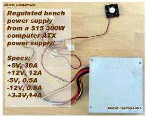
Computer-Netzteile kosten etwa US $15, aber Labornetzteile können Dich US$100 oder mehr kosten! Durch Umbau der billigen (kostenlosen) ATX-Netzteile, die man in jedem weggeworfenen Computer findet, kannst Du ein phänomenales Labornetzteil mit Ausgängen für hohe Ströme, Kurzschlussfestigkeit und sehr genauer Spannungsregelung erhalten.
Vergewissere Dich, bevor Du mit diesem Umbau beginnst, dass das PC-Schaltnetzteil, das Du kaufst oder wiederverwertest, Deinen genügend Ampere liefert. Dies ist besonders wichtig, wenn Du in Deinem RepRap NEMA 17 oder NEMA 23 Schrittmotoren mit hohem Drehmoment verwendest. Ich vermute, dass die meisten RepRaps mit einer 15-Ampere-Versorgung für die +12V auskommen. PC-Schaltnetzteile mit 300 Watt und mehr Nennleistung können so einen Bedarf typischerweise decken. Es sollte beachtet werden, dass der Godzilla RepRap-Entwurf 5 NEMA 17-Schrittmotoren verwendet, die 22 Ampere brauchen. Diese Leistung findest Du erst bei Netzteilen ab 450 Watt, und selbst dann nicht immer. Für so große Systeme solltest Du immer die Technischen Daten des PC-Schaltnetzteil-Modells prüfen, das Du verwenden möchtest. Ich habe eins mit dieser Leistung für Godzilla für US$ 22,95 bekommen und hätte auch eins für nur US$ 16,95 bekommen können. Vergleiche die Preise!
Schritt für Schritt
- Unplug the power cord from the back of the computer. "Harvest" a power supply from a computer by opening up the case of the computer, locating the gray box that is the power supply unit, tracing the wires from the power supply to the boards and devices and disconnecting all the cables by unplugging them.
- Remove the screws (typically 4) that attach the power supply to the computer case and remove the power supply.
- Cut off the connectors (leave a few inches of wire on the connectors so that you can use them later on for other projects).
- Discharge the power supply by stripping the insulation of the ends of a black and a red wire and connecting them together.
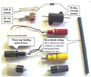
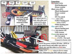
- Get all the parts that you need together, such as the following: binding posts (terminals), a LED with a current limiting resistor, a switch, a power resistor (10 ohm, 10W or greater wattage), and heat shrink tubing.
- Open up the power supply unit by removing the screws connecting the top and the bottom of the PSU case.
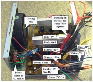
- Bundle wires of the same colors together. IMPORTANT: Make sure that the lone brown sense wire is bundled with the orange wire. If the brown wire is tied to 3.3V, the power supply will produce an output.
- The color code for the wires is: Red = +5V, Black = 0V, Yellow = +12V, Blue = -12V, Brown = Sense (tie to 3.3V), Orange = +3.3V, Purple = +5V Standby (not used), Gray = power is on, and Green = Turn DC on.
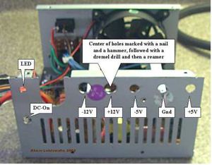
- Drill holes in a free area of the power supply case by marking the center of the holes with a nail and a tap from the hammer. Use a dremel to drill the starting holes followed by a hand reamer to enlarge the holes till they are the right size by test fitting the binding posts. Also drill holes for the power ON LED and a Power switch.
- Screw the binding posts into their corresponding holes and attach the nut on the back.
- Connect all the pieces together.
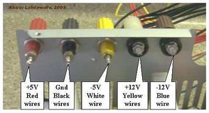
- Connect one of the red wires to the power resistor, all the remaining red wires to the red binding posts;
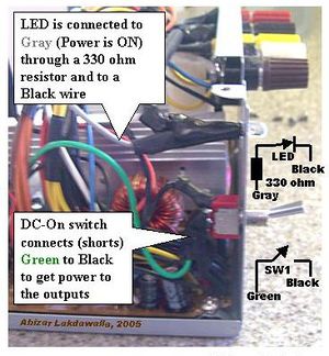
- connect one of the black wires to the other end of the power resistor, one black wire to a resistor (330 ohm) attached anode of the LED, one black wire to the DC-On switch, all the remaining black wires to the black binding post;
- connect the white to the -5V binding post, yellow to the +12V binding post, the blue to the -12V binding post, the gray to the cathode of the LED;
- connect the green wire to the other terminal on the switch; and hook up the orange wires with the brown.
- Make sure that the soldered ends are insulated in heatshrink tubing.
- Organize the wires with a lot of electrical tape.
- Make sure that all the connections look good. Put a drop of superglue to stick the LED to its hole. Put the cover on.
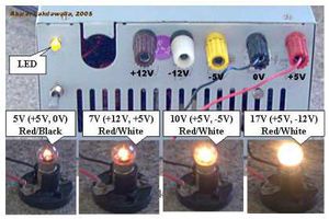
- Plug in the IEC power cord into the back and into an AC socket. Switch on the main switch on the PSU. Check to see if the LED light comes on. If it has not, then power up by flipping the switch that you had placed on the front. Plug in a 12V bulb into the different sockets to see if the PSU worked, also check with a digital voltmeter. It should look good and work like a charm!
Tipps
- OPTIONS: You don't need an additional switch, just connect the green and a black wire together. The PSU will be continuously on. You also don't need an LED, just ignore the gray wire. Cut it short and insulate it from the rest.
- In the older ATX power supplies, the brown sense wire needs to be attached to the 5v wire for the PSU to work.
- In some cases, you may find that there is no brown wire. However, if you get a pin-out of an ATX motherboard connector, you can see which wire is the sensor wire (pin 11.) If not brown, this wire is probably orange.
- If the power supply does not work, that is, no LED light, check to see if the fan has come on. If the fan in the power supply is on, then the LED may have been wired wrong (the positive and negative leads of the LED may have been switched). Open the power supply case and flip the purple or gray wires on the LED around (make sure that you do not bypass the LED resistor).
- If you are not sure of the power supply, test it in the computer before you harvest. Does the computer power on? Does the PSU fan come on? You can place your voltmeter leads into an extra plug (for disk drives). It should read close to 5V (between red and black wires). A supply that you have pulled may look dead because it does not have a load on its outputs and the enable output may not be grounded (green wire).
- The power resistor needs to be attached to the metal body as it gets pretty warm and needs to be kept cool by conduction. If you cannot attach the resistor with a screw, attach the resistor by tying it to a ventilation slot with twist ties or large diameter copper wire.
- Feel free to add some pizzaz to the dull gray box.
- You can also convert this to a VARIABLE POWER SUPPLY - but that is another article (hint: Uses a 317 IC with power transistor).
- The voltages that can be output by this unit are 5v (+5, 0), 7v (+12, +5), 10v (+5, -5), 12v (+12, 0,) 17v (+5, -12) and 24v (+12, -12) which should be sufficient for most electrical testing.
- You can add a 3.3 volt output to the supply by hooking the orange wires to a post (make sure the brown wire remains connected to the orange bundle) but beware that they share the same power output as the 5 volt, and thus you must not exceed the total power output of these two outputs.
Warnings
- Line voltage can kill. Make sure that you have removed the power cord before doing the conversion and have discharged the capacitors by tying the +5V to ground or by shorting the capacitors with the power resistor or with screwdriver.
Things You'll Need
- An obsolete computer with an ATX 250W, 300W or 400W power supply.
- Wire cutters, needle nose pliers, drill, reamer, soldering wire, soldering iron, electrical tape, heat shrink tubing
- Binding posts for output terminals, LED, current limiting resistor for the LED, power resistor to load the power supply, a low wattage switch.
Einfache dauerhafte Modifikationen
Wie hier besprochen.
Um das unvermeidliche Stolpern über lose Kabel zu verhindern, ist es eine gute Idee, Deine Kabel auf eine dauerhaftere Weise zu verlegen, nachdem Du bestätigt hast, dass das Netzteil (PSU = Power Supply Unit) funktioniert. Dies ist eine Möglichkeit, dies zu tun.
- Eigenschaften des Aufbaus:
- Klebeband, um jedes eventuelle Verhaken von Leitungen zu vermeiden und um den Schalter zu sichern. Nicht die Belüftungsdurchbrüche zukleben, da der Luftstrom für den Betrieb notwendig ist!
- Ein großer Not-Aus-Schalter, der leicht zugänglich ist.
- Der Lüfter dieses 250-W-Netzteils ist sehr leise, daher wurde eine LED als Einschaltanzeige hinzugefügt.
- Ungenutzte Leitungen werden in einem Kasten an der Seite verstaut, falls sie später benötigt werden. Wenn Du sicher bist, dass Du sie nicht mehr brauchst, kannst Du sie abschneiden, um den Aufbau noch ordentlicher zu machen, denke jedoch daran, die Enden zu isolieren, um Kurzschlüsse zu vermeiden.
- Leichter Anschluss an den Reprap mit dem Original-Molex-Steckverbinder.
- Ein Kabelbinder fixiert den Molex-Steckverbinder, damit beim Lösen des Steckers keine Leitungen abgerissen werden.
- Verkabelung
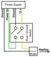
- Wird die Leitung "Power on" mit "Ground" verbunden, schaltet sich das Netzteil ein, und aus.
- Das Trennen der 12V-Leitung schaltet den Strom ein paar unbedeutende Mikrosekunden früher aus, da in den Kondensatoren des Netzteil noch eine Restladung ist. Aber wenn Du keinen zweipoligen Schalter (für die 12V-Leitung und die Ground-Einschaltleitung) hast, den Du wirklich verwenden willst, kannst Du auch einfach die 12V-Leitung so lassen, wie sie ist.
- Wenn Du eine Molex-Buchse herumliegen hast, kannst Du den Molex-Stecker des Netzteils direkt verwenden, um die Verbindung leicht lösen zu können.
- Denke daran, den Aufbau und die Ausgänge mit einem Voltmeter zu prüfen, bevor Du Deinen Mendel daran anschließt!
- Weitere Ideen
- Bringe am RepRap einen stolperfesten Steckverbinder an, damit Du die Elektronik nicht zerstörst, wenn doch einmal jemand über das Kabel stolpert.
- Bringe mehrere Schalter und Steckverbinder an, damit Du mehrere Maschinen an eine PSU anschließen kannst.
- Mehr Klebeband.
