LongboatPrusa
|
English • العربية • български • català • čeština • Deutsch • Ελληνικά • español • فارسی • français • hrvatski • magyar • italiano • română • 日本語 • 한국어 • lietuvių • Nederlands • norsk • polski • português • русский • Türkçe • українська • 中文(中国大陆) • 中文(台灣) • עברית • azərbaycanca • |
translations: Brazilian portuguese
Release status: Working

| Description | LM8UU Linear Bearing
Based Prusa.
|
| License | GPL
|
| Author | |
| Contributors | |
| Based-on | |
| Categories | |
| CAD Models | Coming soon.
|
| External Link |
The Longboat Prusa, is a Prusa Mendel variant which uses LM8UU linear bearings on all axes. It has a 4mm aluminium heated print bed, Y axis carriage and X axis carriage.
This is not the version shipped by thereprapstore in 2012! If you are looking for those instructions go ABSPrusa
Contents
Bill of Materials
Printed Plastics
| Quantity | Description | Type | Comments | Diagram |
|---|---|---|---|---|
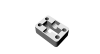
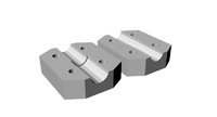
| 4 | coupling | RP | 
| |
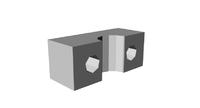
| 8 | LM8UU holder | RP | 
| |
| 3 | endstop-holder | RP | 
| |
| 1 | LM8UU x-end-idler | RP | 
| |
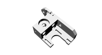
| 1 | LM8UU x-end-motor | RP | 
| |
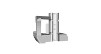
| 1 | y motor bracket | RP | 
| |
| 2 | z motor-mount | RP | 
| |
| 4 | belt clamp | RP | 
| |
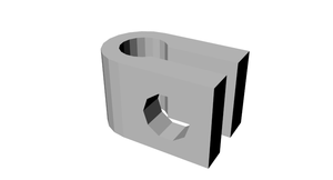
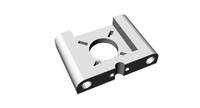
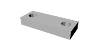
| 8 | bar clamp | RP | 
| |
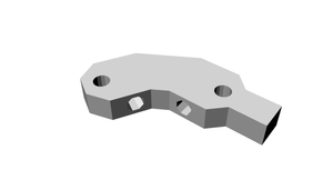
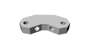
| 2 | rod clamp | RP | 
| |
| 2 | pulley | RP | 
| |
| 4 | frame-vertex with foot | RP | 
| |
| 2 | frame-vertex | RP | 
| |
| 1 | extruder block | RP | 
| |
| 1 | extruder idler block | RP | 
| |
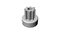
| 1 | drive gear | RP | 
| |
| 1 | hub gear | RP | 
|
Smooth Rod
- 2x 410mm 8mm stainless steel round bar
- 2x 406mm 8mm stainless steel round bar
- 2x 350mm 8mm stainless steel round bar
Threaded Rod
- 6x 370mm M8 Threaded rod
- 4X 294mm M8 Threaded rod
- 3x 440mm M8 Threaded rod
- 2x 210mm M8 Threaded rod
- 1x 50mm M8 Threaded rod
- 1x 20mm M8 Threaded rod
Nuts, Bolts & Washers
- 100x M8 Nut
- 100x M8 Washer
- 5x M8 Mudguard washer
- 1x M8 Nyloc Nut
- 15x M4 nut
- 10x M4 Nyloc Nut
- 10x M4 Washer
- 4x M4 Wing Nut
- 3x M4 Bolt16
- 4x M4 Bolt50
- 6x M4 CSK Machine Screw 40mm
- 40x M3 Washer
- 80x M3 Nut
- 3x M3 Machine Screw 8mm
- 20x M3 Machine Screw 10mm
- 30x M3 Machine Screw 16mm
- 20x M3 Machine Screw 20mm
- 25x M3 CSK Machine Screw 12mm
- 2x M3 CSK Machine Screw 16mm
- 3x M3 Grub Screw 6mm
Belts
- 840mm x 5x T5 pitch timing belt
- 900mm x 5x T5 pitch timing belt
Bearings
- 6x 608zz
- 1x 624zz bearing
- 12x LM8UU Liner
Thick Sheet
- 1x 4mm aluminium heated print bed
100px Media:Longboat-Prusa-heated-print-bed.dxf
- 1x 4mm aluminium X-plate
200px Media:Longboat-Prusa-X-Plate.dxf
- 1x 4mm aluminium Y-plate
200px Media:Longboat-Prusa-Y-Plate.dxf
Heated bed parts
- 4x 1R HS25 resistors. HS25 1R J
Hot End parts
Electronics
- The Longboat Prusa is supplied with Sanguinololu 1.3a electronics but any other electronics should work fine.
Steppers
- 5x NEMA 17 Bipolar stepper motors - SY42STH47-1684A
Assembly
Below are the assembly instructions for Batch 2 and 3. For historic purposes the Batch 1 assembly instructions can be found LongboatPrusaBatch1 here
Alternative build guides
There is also a great blog by Brian here detailing the build of his Longboat Prusa, with lots a photos.
Frame assembly
In this section we will be looking at the frame assembly.
NOTE: Even if you have assembled a RepRap Prusa before please read these instructions as our frame differers slightly from the standard Prusa.
Tools
- 30cm Rule
- M8 Spanner
- Adjustable Spanner
- M4 Spanner (not enough room for adjustable)
- Stanley Knife and/or Sandpaper
- Wire Cutters
- Wire Strippers
- A Crimping tool and/or Long Nose Pliers
- A Dremel is useful for trimming the M8 mudguard washers
- T6 Torx head
- Heat gun (or hair dryer / hot water)
- 4mm drill bit
Step 1 Frame triangles
Components
- 4x Frame Vertex with foot
- 2x Frame Vertex
- 2x Bar clamps
- 6x 370mm M8 Threaded rod
- 28x M8 Nuts Bag 1
- 28x M8 Washers Bag 2
Instructions
Divide the above components in to two even sets.
Take one of the lengths of threaded rod and slide a bar clamp to the middle (see the photo to understand how the bar clamp attaches to the threaded rod). Place a washer and then a nut either side of the clamp.

Place a nut, washer and then a frame vertex with foot followed by a washer and the nut on to each end of the rod. Loosely tighten the nuts.


Attach two more lengths of threaded rod to each footed frame vertex, using a washer and nut either side as before.


Attach a non footed frame vertex to the connect up the triangle.
Repeat all the above instructions until you have two matching frame triangles.

Place each frame flat on you desk, using your ruler tighten the nuts until each side is 290mm (measure from plastic to plastic)

Step 2 Cross Bars
Components
- 4x Bar clamps
- 1x Y Motor bracket

- 2x 608zz Bearings
- 4x 294mm M8 Threaded rod
- 14x M8 Nuts Bag1
- 15x M8 Washers Bag2
- 4x M8 Mudguard Washers Bag 3
Instructions
Take the Y motor mount and attach a 294mm length of rod through the bottom hole, approximately half way along the rod. Fix in place with a M8 washer and M8 nut either side.

Take a Bar clamp and attach in to a 294mm length of rod, approximately a quarter of the way in from one end. Fix in place with a M8 washer and M8 nut either side. Then attach a M8 nut and M8 washer half way down the rod. Attach this rod through the top hole of the Y motor mount.

Add the following components, a M8 Mudguard washer, M8 washer, 608zz bearing, M8 washer, M8 Mudguard washer and then a nut.

Add a bar clamp to the rod attaching with a M8 washer and M8 nut either side.

On a new 294mm length of rod attach a 608zz bearing, followed by a M8 washer, M8 Mudguard washer and M8 nut either side. Attach the remaining two bar claps either side of this, attaching with M8 washers and M8 nuts either side.

Step 3 Frame assembly and jigging
Components
- 26x M8 Nuts
- 24x M8 Washers
- 3x 440mm Threaded Rod
Instructions
Take the rod assembly which has the two rods held apart by the Y motor mount, add a M8 nut followed by a M8 washer.

Take one of the frame triangles made earlier and attach the Y motor mount rod assembly through the holes in the frame vertex with foot. Attach in place with M8 washers and M8 nuts.

Attach the two remaining 294mm assembles to the other frame vertex with foot the same way as above. Note make sure the rods with the 608zz bearings are above the rods without bearings.

Prepare the opposite ends with M8 nut and M8 washer, attach the other frame triangle. Before attaching in place with a M8 washer and M8 nut measure the gap between the footed frame vertex's it needs to be 234mm from the inside to inside of the plastic frame vertex.


Stand the frame on the footed frame vertex's. Take a 440mm length of threaded rod slide half way through one of the holes on one of the non footed frame vertex, add a M8 washer, two M8 nuts and finally a washer. Slide this all the way through the opposite frame vertex hole. Turn the frame so that the side with the Y motor mount is facing you. Check that the spacing between the inside of the plastic frame vertex is 234mm as before. Maintaining this measurement adjust the rod so that there is 95mm of rod on the right side, measure from the out side of the plastic frame vertex. Add a M8 washer and M8 nut to secure this rod in place at each end. Repeat this process with the second 440mm length.

The four bar clamps now need to be spaced correctly, measuring from the inside of the nearest frame vertex, the nearest side of the the bar camp needs to be 40mm. The inside M8 washer and nut do not need to be secured yet, so just tighten them enough to secure the bar clamp.

With the Y motor mount facing you the distance from the inside of the right frame vertex to the first mud guard washer needs to be 112mm.

The two bar clamps on the bottom of the frame triangles now need spacing correctly. The distance from the frame vertex to the bar clamp needs to be 129mm. NOTE measure from the frame vertex which is on the same side as the Y motor mount.

Now take the last 440mm length of threaded rod and screw it through the bar clamps. Turn the frame so that the side with the Y motor mount is facing you. There need to be 100mm of threaded rod on the right side, adjust the rod unit there is 100mm past the outside edge of the bar clamp. (Please note the photo shows 95mm and is incorrect)

Keeping the frame so that the Y motor mount facing you, add a further three M8 nut and one M8 washer to the upper right sides of the 440mm threaded lengths. Add one M8 washer to the upper left sides.


Step 4 Z axis mounts
Components
- 2x Z motor mounts
- 2x Rod clamps
- 2x Bar clamps
- 4x M3 20mm screw
- 4x M3 nut
- 4x M3 washer
Instructions
Insert a M3 nut in to each of the nut sized holes on the inside of the two Z motor mounts.

Attach a rod clamp to each of the Z motor mounts using two M3 20mm screws each with a washer.


Attach each a Z motor mount to either side of the upper 440mm threaded rods and attach in place with a M8 washer and M8 nut.


Keeping the frame so that the Y motor mount is facing you, add a M8 nut and M8 washer to the right side of the lower 440mm threaded bar, attach to this a bar clamp, and attach in place with a M8 washer and M8 nut. Repeat on the left side.

The inside edge of the bar clamp on the right side needs to be 72mm from the out side of the nearest bar clamp.

The inside edge of the bar clamp on the left side needs to be 61mm from the out side of the nearest bar clamp.

Y axis assembly
Y axis plate
Components
- 4x LM8UU holder

- 2x Belt clamps
- 4x LM8UU linear bearing
- 20x M3 nut
- 20x M3 washer
- 20x M3 16mm screw
- 1x Y axis aluminium plate
- 2x 406mm stainless steel smooth rod
Instructions
Preparing the LM8UU holders.
Firstly due to the way the LM8UU holders are printed they do not rest perfectly flat. Use a knife in a safe manner to scrape the middle of the bottom side until it will sit on a flat surface without rocking. An alternative approach is to put some sand paper flat on a table and gently run the LM8UU holders against it until they no longer wobble.
In the next step you will glue the LM8UU bearings in the holders, so ensure all eight holders rest perfectly flat.

Use super glue or a suitable plastic adhesive (not supplied) to glue in place the LM8UU linear bearings, it only requires a small amount to hold the bearings in place. Apply the glue to the plastic part not the metal bearing. Twist the bearing as you push it in to spread the glue around. Wipe off any excess glue and allow to dry. Do all eight LM8UU holders at the same time. Be careful with the glue.

Attach each of the four LM8UU holder to the aluminium plate using the M3 16mm screws, the M3 washers go between the screw head and the aluminium plate.


Attach the two belt clamps but do not fully tighten, attach with two M3 16mm screws with M3 washers and M3 nuts, the plastic clamp needs to be on the opposite side to the LM8UU holders.


Take the two 406mm stainless steel round bars and slide them half way through the bar clamps which are either side of the Y motor mount.

Take the Y axis aluminium plate assembly and slide the two 410mm bars through the LM8UU bearings, continue to slide the rods until they pass through the opposite bar clamps. Space the spare round so that there is an even amount on either side.


Tighten the rod clamps and check the measurements are still correct, between 40mm and 41mm from the inside of the frame vertex to the inside of the rod clamp. Slide the Y assembly back and forth. If you feel any resistance slightly slacken the screws holding the LM8UU holders to the plate and then re-tighten, this ensures that the holders are seated properly.
Y motor installation
Components
- 1x Pulley
- 1x stepper motor (90cm cable)
- 3x M3 10mm screw
- 1x 840mm T5 timing belt
Instructions
Coil the stepper motor cable neatly, it will be terminated along with all the others in the Wiring section.
Attach the pulley to the shaft of the stepper motor, ensuring the grub screw in the pulley lines up with the flat section on the shaft. Fit the pulley as shown in the photo below.

Attach the stepper motor to the left side of the Y motor mount using three M3 10mm screws. NOTE: The M8 mudguard washer may interfere with the M3 screw. One solution is to trim 2-3mm from the mudguard washer using a Dremel cutting tool to allow the M3 screw to freely secure the motor in place.

Slide the Y plate assembly all the way to the Y motor mount, pass the 840mm T5 timing belt underneath the Y plate assembly. Pass the belt over the pulley (make sure the belt teeth face the pulley teeth) pass over the bearing and under the belt clamp. Ensure at least a 1cm passes past the belt clamp. Using a spanner to hold the nut tighten down the belt clamp with the screws.


Repeat the process on the opposite side, the belt need to be tensioned so that there is little or no slack. (a second pair of hands is useful for this)

Hot End Assembly
Components
- 1x brass heater block
- 1x brass nozzle
- 1x PEEK support block
- 1x PTFE insulator
- 1x Thermistor
- 1x Heating resistor
- 1x PTFE tape
- 1x Silicone sealant
Instructions
Take the PTFE insulator and wrap a few turns of the PTFE tape around the threaded section.


Take the brass nozzle and screw on to the PTFE insulator.

Using the Silicone sealant fix the heating resistor in to the smooth board hole in the brass heater block.

Wiring the Hot End
From the spare wire cut from the stepper motors cut four different colours all 75cm in length.
Solder two of the wires to the Thermistor. (NOTE: be careful it is easy to snap the legs off the thermistor)

Use PTFE tape to insulate each leg. The use more PTFE to bind together each leg.


Wrap a cm sized square of PTFE tape around the top of the thermistor. Fill the hole in the heater block with silicone and wipe off any excess so that just the hole has silicone in it. Push the end of the thermistor into the hole. Cut a piece of Kapton take and tape down the trailing wire at 90 degrees to the hole. Leave to set (NOTE from now on be very care full with the heater block as the thermistor's legs can brake easily, never hang the block by the cable)


Use two bootlace ferrules to attach the remaining two 75cm wire to each leg of the heating resistor. Squeeze and twist the ferrules so that the hold the wire to the leg with pilers. Use PTFE tape to insulate the join. (NOTE as with the thermistor wires do not dangle the heating block by the resistor wire)
Extruder Assembly
Components
- 1x Extruder block
- 1x Extruder idler block
- 1x Drive gear

- 1x Hub gear

- 4x LM8UU holder
- 2x Belt clamp
- 4x LM8UU bearing
- 3x 608zz bearing
- 1x Hobbed bolt
- 1x X axis aluminium plate
- 1x Hot End assembly
- 2x M4 counter sunk 40mm screw
- 2x M4 16mm bolt
- 2x M4 nut
- 4x M4 nyloc nut
- 4x M4 50mm bolt
- 3x M3 8mm screw
- 4x M3 16mm screw
- 4x M3 nut
- 3x M8 washer
- 1x M8 nyloc nut
- 1x M8 nut
- 1x 20mm Threaded Rod
Instructions
Take the two M4 counter sunk 40mm screws and attach to the X axis plate through the countersunk holes , fix in place with a M4 nyloc nut on the underside.


Attach the LM8UU holders using the M3 12mm countersunk screws and M3 nuts.


Push two 608zz bearings in the holes on the Extruder block. (NOTE this can be a tight fit, gently squeezing in a vice can help ensure the 608zz bearings are seated correctly)

Use the two M4 16mm bolts to attach the extruder block to the X axis plate and use two M4 nyloc nuts to secure it in place.


Attach the Drive gear to the extruder stepper motor ensuring the grub screw lines up with the flat section of the stepper motor shaft. Fit as shown in photo below.

Attach the four M4 50mm bolts through the bolt shaped holes on the extruder block. Hot End assembly

Take the hobbed bolt and attach the Hub gear to it. Add two M8 washers.

Attach the hobbed bolt assembly to the extruder block, attaching to the side of the extruder block with the motor mount.

Take the extruder stepper motor and hold in place so that the gears engage with each other. You will note that two of the stepper mounting holes are covered by the Hub gear, use one M3 8mm screw to hold the stepper motor in place. Remove the drive gear from the motor shaft, and then remove the hobbed bolt assembly. Attach the stepper motor in place with the remaining two M3 8mm screws which holes are now no longer covered.


Re attach the hobbed bolt assembly, fix in place with one M8 washer, one M8 nut and one M8 nyloc nut.


Re attach the drive gear to the stepper motor shaft, ensuring the grub screw lines up with the flat section of the motor shaft.

Attach the two belt clamps using four M3 16mm screws and four M3 nuts, do not fully tighten yet.


Insert a 608zz bearing with the 20mm threaded rod and attach the Extruder idler holder to the extruder block to hold it in place.

Add a spring to each of the bolts followed by a M4 wing nut. Do not over tighten.


Attaching the Hot End to the Extruder
Take the assembled Brass nozzle and PTFE insulator and push in the hole in the underside of the extruder.

Add the PEEK support block, making sure it seats on the rim of the brass nozzle correctly.


Use two M4 nuts to hold in place. Tighten until the ends of the bolts are in line with the beginning of the threaded section of the brass nozzle. (NOTE any further and the brass nozzle block will make contact with the bolts)

Note that the nozzle should be put into the narrow end of the hole in the PEEK block, otherwise the block will not support the nozzle properly. That is, the narrow end will be towards the extruder assembly and the wide end towards the tip. The wider part of the hole is intended to provide an air space for greater insulation. See this description.
Z axis installation
Components
- 2x coupling set
- 2x Z axis steppers
- 2x clear plastic tube
- 8x M3 10mm screw
- 8x M3 20mm screw
- 16x M3 washer
- 8x M3 nut
- 4x M8 nut
- 2x 210mm threaded rod
- 2x 350mm stainless steel round bar
Instructions
Take the clear plastic tubing and cut it into two equal pieces. Holding this with pliers gently warm them with a hair dryer (or heat gun, or in hot water). Once they are warm, slide them down the shafts of the two Z axis steppers until the free end of the shaft is level with the end of the sleeve.

Temporarily remove the Z motor mounts from the top of each side of the frame, place these upside down on the Z axis steppers, attach to the steppers with M3 10mm screws and M3 washers. Re attach the Z motor mount assemblies to the frame. (Alternatively, it is possible to complete this step without removing the Z motor mounts, by placing the stepper motors on top of the Z motor mounts and screwing the M3 10mm screws with M3 washers up into the stepper motor)


Take the two different sides of the couplers and assemble with M3 20mm screws, M3 washers and M3nuts, test assemble and screw all the way together so that the M3 nuts become fully trapped in the nut shaped holes. Then disassemble. Take the 210mm lengths of threaded rod and trap this inside the coupling as shown in the photo. Tighten just enough so that the rod is held in place. Add a M8 nut as shown in the photo.


X axis assembly
X axis Idler assembly
Components
- 1x LM8UU X-end idler
- 1x LM8UU X-end motor
- 4x LM8UU linear bearings
- 4x cable ties
- 1x 624zz bearing
- 1x 608zz bearing
- 1x M8 mudguard washer
- 2x M8 nut
- 3x M8 washer
- 1x 50mm M8 threaded rod
- 1x M4 16mm bolt
- 1x M4 Nyloc nut
- 3x M4 washer
Instructions
Take the four LM8UU bearings and push them in to the X-end idler and X-end motor plastic parts.

When snapping in the LM8UU bearings occasionally the plastic part around the base can crack, however this is easily fixable with super glue and does not effect the operation of the part.


Use the supplied cable ties to fix in place.


The X-end idler bracket may need a 4mm hole drilling in for attaching the 624zz bearing, this hole was added after some machines shipped.
Looking at the piece as orientated in the photo measure up from the bottom 19mm and then in 5mm this will give you the centre of the 4mm hole, drill this slowly.


Place the M4 16mm bolt through the hole. Add two M4 washer followed by the 624zz bearing followed by a M4 washer and secure in place with a M4 nyloc nut.


Attach the M8 50mm threaded length of rod through the large hole attach to the inside with a M8 washer and M8 nut.

On the outside add a M8 washer followed by a 608zz bearing followed by a M8 washer, M8 mudguard washer, held in place with a M8 nut.

I found that the M8 washers pushed the large bearing out too far and left too big a gap before the mudguard washer, with the result that the belt did not stay on the smaller bearing. I replaced the M8 washers with washer-shaped pieces cut from thin plastic.
I then found that the two bearings were too close together for the thickness of the drive belt. The X axis wouldn't move smoothly and steps were skipped. Perhaps I drilled the hole in slightly the wrong place, or perhaps there just isn't enough space. As a temporary solution I have removed the small (624zz) bearing and added a bunch of M4 washers instead; this seems to have cured the skipping.
X axis sub assembly
Components
- 1x X-end Idler assembly
- 1x X-end motor
- 1x Stepper
- 2x 410mm stainless steel round bar
- 2x 350mm stainless steel round bar
- 3x M3 10mm screws
- 1x Pulley
- 1x 900mm T5 timing belt
- 2x M8 nut
Instructions
Stand the Extruder assembly in the roll of Kapton tape as shown in the photo so that the large gear is facing you.

Attach the two 410mm smooth rods through the LM8UU bearings.

Slacken off the screws holding the LM8UU holders then re tighten this makes sure they are correctly aligned on the rods.
Attach the X-end idler assembly to the left end of the rods ensuring they slide all the way to the end.

Attach the X-end motor holder to the right side.

Stand this hole assembly on the middle of the Y-axis plate as shown in the photo.

Attach the other end of the coupler to the Z motor shaft, making sure the other end of the threaded rod has located through the X ends. Do this to both sides.

Take the 350mm stainless steel slide down through the rod clamp in the Z motor mount, through the LM8UU bearings in the X ends and down to the rod clamp. Do this on both sides.

Add a nut to the bottom of the 210mm lengths of threaded rod thread up until this sits in side the nut shaped gap on the bottom of the X end idler and the X end motor side. You can now remove the role of Kapton tape.


Attach a belt pulley to the motor shaft as shown in the photo below and attach the to the X end motor holder, with three M3 10mm screws.

With the geared side of the extruder now facing you slide the extruder to the same side as the idler X end. Attach the 900mm length of T5 belting to the left side belt clamp on the X chassis plate. Remove the M8 nut and mudguard washer from the X end idler so that you can pass the belt over the 624zz bearing and under the 609zz bearing, and then reattach the mudguard washer and M8 nut. Tighten down the belt holder with a screw driver while holder the nut still with a spanner.


Feed the belt over the pulley on the motor shaft and attach to the x chassis with the right side belt clamp, the belt needs to be reasonably tight. NOTE there will be several centimetres of excess belt that will need to be trimmed.


Heated Bed wiring
Use the supplied 16 AWG wire to connect each of the resistors as shown in the photo.

Wrap each solder joint with PTFE tape.
Cut two lengths of one colour of 5cm wire, spare from the steppers and solder one end of each wire to the middle leg of the MOSFET.
Attach one to the choc block third terminal from the left. Attach the second to the 1Megohm resistor using a bootlace ferrule.

Cut two more lengths of 5cm wire, both the same colour but different from the colour above. Using a bootlace ferrule attach these two wires to the remaining side of the 1M resistor.

Solder one of these wires to the right leg of the MOSFET, and attach the remaining one to the choc block, second terminal from the left.
Using the 16 AWG wire attach the left MOSFET leg to the terminal of the bottom left heat resistor nearest to the centre of the plate.

MOSFET notes from one builder
The IRF 2804 MOSFET as fitted (heatsink down, wires at bottom) connections are from left to right: GATE DRAIN SOURCE
GATE should connect to the +12V bed output from the sanguinololu, and is pulled high by the 1M resistor. DRAIN should connect to +12V fixed supply SOURCE
Using the FET as a switch, the gate would normally be pulled down by a resistor to 0V so it defaults to off, but this might be done to make sure it turns off fully when the electronic output is less than 12V. It will dissipate more power in the FET, but it seems well rated (75A on a heatsink) so maybe this is intentional or is intended to make a simple constant current supply? It seems more likely that it's a simple typo or misreading the datasheet for the TO-220 package:
If gate is pulled to +12V, the 1.4 ohm load (4 x 5.6 in parallel) will pull the source down to around 7.5V (see datasheet Figure 1). That will give about 40W dissipated by the resistors (10W each), and 24W dissipated by the FET (5A, 4.5V), which would heat the bed unevenly. I'd guess the loosely fitted connection from FET to heated bed will do no better than 3°C per Watt, so would also raise the junction temperature to around 100°C. In turn, that will reduce the threshold voltage, reducing the actual power dissipated, so it might not damage anything and won't thermally runaway.
However, I've changed my layout to swap the drain and source from the above instructions, which should increase current through the resistors to 8.6A (25W per resistor, full rated power), and reduce power dissipated by the FET to 0.17W
I don't have a circuit diagram, but the resulting configuration is:
- Unswitched +12V to one end of the power resistors
- The other end of the resistors connected to drain
- Switched supply from electronics to gate with pulldown to source
- 0V from power supply to source
Here is a circuit diagram and a photo for my interpretation of the above configuration, which seems to work for me:


It doesn't look like the Sanguinololu board traces will carry 10A, so I will make the 12V connections direct to the power supply.
If this works (and I remember!), I will update the build instructions above. Until then, you may choose to attempt this entirely at your own risk, this is not an official mod from the RepRapStore or me or anyone else and may be a catastrophically bad idea!
Heat bed installation
Components
- 4x M4 40mm countersunk screws
- 4x M4 Nyloc nut
- 8x M4 nut
Instructions
Pass a M4 40mm countersunk screw through the countersunk hole in the print bed and a fix firmly in place with an M4 nut.


Add a second M4 nut to each of the screws, thread it down approximately 10mm of the screw.

Rotate the bed so that the choc block is facing the side away from the Y motor, align the screws with the holes on the Y chassis. Attach with a M4 Nyloc on the bottom of each of the screws. The M4 Nylocs need to be flush with the bottom of the screw, then adjust the middle M4 nut so that it is tight against the Y chassis.


Assuming your build surface is level, use a small spirit level to check the frame is sitting level the best place to check is the top two 440mm threaded rods, or the Z axis motors. If your build surface is not level use paper shims under the frame feet to level the frame. Once the frame is sitting level check the print bed is level. Check level from left to right and front to back. If it is not level adjust the nuts either side of the Y chassis plate.
Electronics and Wiring
Sanguinololu board modification
Because the heated bed has its own driver transistor mounted on it, you don't need the one on the Sanguinololu board (Q2 on the Sanguinololu circuit diagram). Remove Q2 (desolder or cut legs) and replace it with a link as shown in the image. This takes the 5V microcontroller output (D14) to drive the transistor directly to the connector on the edge of the board (labeled -V on the board). From there it can be wired to "controller heated bed" on the heated bed (see the heated bed circuit diagram above).

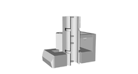
Fitting electronics
- Sanguinololu board
- 4 M3 12mm CSK screws (bag 15)
- 4 M3 nut (bag 11)
- 8 ty-raps
These instructions assume you want the electronics fitted at the opposite end to the Y motor, as shown in the picture at the top of the page.
Turn the printer around so the Y motor faces away from you
Remove any protective film from the electronics mounting plate and lay it flat with the electronics board screw holes at the left side.
Fit the Sanguinololu board with components on top and USB socket facing away from you using M3 12mm CSK screws inserted from the board side and M3 nuts on the rear of the plate. Do not overtighten the screws, as this will deform the PCB and could break tracks.
Feed 4 ty-raps through the holes at each end of the plate- up from below, through the holes nearest the centre of the plate, leaving approx 20mm behind the plate, and then push the free end down through the outer sets of holes (this way leaves a neater job when the ty-raps are secured and cut).
Hold the plate about 1cm below the end of the threaded rod end at the top frame vertex on each side, and secure the ty-raps around the threaded rod (if the plate is fitted tight against the top vertex, it may limit the Z axis movement and make it difficult to fit the USB connector).
Stepper motor cable routing
Route the cables from each stepper motor to the corresponding labelled connector on the electronics board:
- The two Z steppers and the Y stepper are fixed so can be routed along any section of the frame where they will not catch on other moving parts.
- The X stepper motor moves up and down the Z axis, attach its cable to the frame rod running down from the left side of the electronics plate, at a position about 100mm from the bottom vertex, with about 50mm slack, this should allow movement from top to bottom of the Z axis without leaving excessive slack
- The extruder motor moves in the Z and X axes, route its cable in free air to the electronics board, ensuring it can reach all 4 corners of its possible movement without snagging the cable
Attach the cables neatly to the frame with ty-raps or the supplied cable snake.
Stepper motor preparation
The steppers are supplied with much more wire than required. You well need to cut the stepper wires to the required lengths below or fix the cables to the frame following the above section then cut to length:
- Y axis stepper 90cm
- X axis stepper 45cm
- Z axis steppers 25cm (there are 2 of these)
- Extruder stepper 55cm
Molex connector attachment
- 15 Molex crimp terminals (supplied on a strip)
- 5 4-pin Molex housings
Next the steppers need their Molex connectors attaching
Start by attaching the crimps to the ends of the wire. There is a great video here explaining how to do this.
Next gently push the crimps in the connector housing. This can be quite tricky with poor quality crimps.
Some (poor quality) crimps are more difficult to fit than others. The easiest connectors are joined as a strip on the cable end of the crimp connector rather than the bendy contact end. Maplin sell good quality connectors, reference YW25C. The supplied crimps are joined at the contact end and are quite hard to cut flush (even with good snips) and insert straight. If it doesn't look neat, carefully work the contact back out with a small screwdriver, reshape it, and try again!
With the connector orientated the same way as in the photo the order is
RED BLUE GREEN BLACK

Attaching the end stops
Some reprapers have commented that the standard Prusa Mendel Assembly guide explains how to attach the end stops, although the video illustrates optical stops.
It is possible, with some effort, to use the supplied M3 12mm screws and M3 nuts to attach the microswitch end stops to the h-shaped end stop holders but using a ty-rap may be less difficult.
- 3 h-shaped end stop holders
- 3 microswitches
- Spare cable from stepper motors
- 6 Molex crimp inserts terminals
- 3 Molex 3-way housings
- 3 M3 M/Screw 16mm (bag 13)
- 3 M3 nuts (bag 11)
- 6 ty-raps
Attach each microswitch to the end stop holder using 2 ty-raps (the supplied microswitches and holes appear to be 2.5mm, but no screws this small are included) fitted diagonally:
- One ty-rap fits between the common (C) and normally open (NO) terminals and through the adjacent mounting hole
- One ty-rap goes through the other mounting hole and under the end of the lever. When pulled tight it will not restrict movement of the lever
Solder wires to the terminals as follows (note it is not necessary to connect the middle terminal at either end. The microswitches will work without, but you can use the same wiring loom if you later change to opto endstops if all are wired, and forcing the line to 12V rather than relying on internal pullups should be more robust against noise):
- 2/NC black
- 3/NO red // Not essential for microswitches- see above
- 1/C blue
Solder those joints with the wires coming off at right angles to the microswitch in order to not obstruct the positioning of the end stops. Consider wrapping the soldered joints in PTFE tape or heat shrink collars.
Fit Molex connectors at the electronics end of the cable
- SIG blue
- V+ red // Not essential for microswitches- see above
- 0V black
Repeat for each end stop (if these are not connected, axis motors will only move in one direction.
- Y-stop fitted to Y solid rod at Y motor end, 3-5mm from frame
- Z-stop fitted to Z rod close to bottom, adjust to allow extruder to touch heated bed
- X-stop fitted to X rod close to the motor.
(NB this assumes you want X and Y in the natural directions when the machine is positioned with the Y motor away from you. This will be wrong with the default firmware, which has the X axis going the wrong way in that orientation.)
Use the position of the nozzle to determine the optimal position of the end stops to set the "home" position of the nozzle. The standard Prusa Mendel wiring instructions contain guidance on positioning the end stops.
Commissioning
Coming soon. See Prusa Mendel instructions in the meantime for guidance. Notes here are from one user who hasn't got the printer fully working yet, and should be used with caution (remove this note if you have followed them successfully!)
Short between the green (PS-ON / REMOTE) and the adjacent black (COM / RETURN / 0V) pins on the large power supply connector to turn it on (fan will run when it is on). A short piece of solid core wire or one end of a paperclip is ideal for this.
Verify there is 12V on the 2x2 connector then turn the power supply off, plug the 2x2 connector from the power supply into the matching socket on the electronics board, and connect the USB up to a PC with printrun installed (See the printrun git repository for source, with installation instructions at the bottom including a link to a windows pre-compiled runtime (on my machine, the FTDI USB serial device in the electronics board wasn't recognised by Windows XP, but worked fine in ubuntu 11.10).
Using printrun / pronterface, this should result in a printer that moves when requested using the joystick controls. If it only moves in one direction in each axis but the extruder moves in and out, it's because the limit switches are not fitted (each switch needs to normally hold the SIG line to ground).
Printer Hardware
This post suggests setting Pololu Vref to 0.32V. Supplied settings were 0.5V to 0.6V, take a note of voltages before you change them in case the supplied ones are correct for this kit. On mine, changing to 0.32V stopped the Y motor 'drifting' where each layer was offset, I guessed it was maybe over current and shutting down at some point?
On my machine, the X axis was frequently missing movements when controlled from pronterface (and consequently lost track of position, so it would not move beyond some arbitrary point). The driver chips were around 100C, with the X chip slightly higher. I reduced the voltages to from 0.57-0.60V to around 0.32V (it's hard to get it perfect) by turning the potentiometers about 40 degrees anticlockwise. This reduced the temperatures to around 40C, and so far the X axis seems to be working.
Printer Firmware
The supplied firmware is Sprinter (other firmware is available from the List of Firmware). The supplied firmware should get you up and running to confirm all is wired correctly, but stepper motor and extruder rates and thermistor won't be properly calibrated.
To calibrate the system, you will need to learn how to compile and upload your own firmware via Arduino v0023 and the Sanguino customisations. Arduino v1.0 is not currently compatible with the Sanguino addons. Dust's blog has a clear guide to the required steps
Firmware settings
Please can someone confirm the settings they have altered from defaults in the firmware.
Here is the standard Prusa guide to Commissioning which is a useful reference.
If you are using the Sprinter firmware, you will need to edit Configuration.h with the following modifications:
- Define the motherboard:
#define MOTHERBOARD 62
- Set up the extruder - see
- Define the thermistors:
#define THERMISTORHEATER 6
#define THERMISTORBED 6
- axis_steps_per_unit, shouldn't need editing for X,Y,Z, but extruder should be calibrated following the above extruder link
- Endstop settings - default settings are correct with endstops fitted
- Inverting axis directions - with Y motor closest and using pronterface, all axes and extruder moved in the correct direction with steppers wired as above
- If you have many serial errors, you can try to increase the baud rate to 250000
Thermistor calibration
Here's a look-up table for one thermistor for the firmware :
// RS thermistor 484-0149; EPCOS B57550G103J
// Made with createTemperatureLookup.py (http://svn.reprap.org/trunk/reprap/firmware/Arduino/utilities/createTemperatureLookup.py)
// ./createTemperatureLookup.py --r0=10000 --t0=25 --r1=0 --r2=4700 --beta=3480 --max-adc=1023
// r0: 10000
// t0: 25
// r1: 0
// r2: 4700
// beta: 3480
// max adc: 1023

short bedtemptable[NUMTEMPS][2] = {
   {1, 599},
   {54, 160},
   {107, 123},
   {160, 103},
   {213, 90},
   {266, 79},
   {319, 70},
   {372, 62},
   {425, 55},
   {478, 49},
   {531, 43},
   {584, 37},
   {637, 31},
   {690, 25},
   {743, 19},
   {796, 12},
   {849, 5},
   {902, -3},
   {955, -16},
   {1008, -42}
};
If you are using Sprinter firmware, then you will need to edit this automatically generated code slightly in order to insert it into the thermistortables.h file to replace the existing thermistor table at line 271:
#if (THERMISTORHEATER == 6) || (THERMISTORBED == 6) // 100k Epcos thermistor
#define NUMTEMPS_6 20    // *** note that this is changed to 20
const short temptable_6[NUMTEMPS_6][2] = {   // note that the name of the table is changed to replace the existing table
   {1, 599},
   {54, 160},
   {107, 123},
   {160, 103},
   {213, 90},
   {266, 79},
   {319, 70},
   {372, 62},
   {425, 55},
   {478, 49},
   {531, 43},
   {584, 37},
   {637, 31},
   {690, 25},
   {743, 19},
   {796, 12},
   {849, 5},
   {902, -3},
   {955, -16},
   {1008, -42}
};
The Batch 3 and Batch 4 units despatched early 2012 with 2K thermistors. 100K should follow shortly
- Warning, following is for information only, do at your own risk* - In the meantime it is possible to add 100R resistors across R9 and R10 to make the 2K ones usable (if, like me, you are desparate to get printing!). As noted in this build forum post there's a problem with that which could affect temperature accuracy and damage the thermistor, but it did get me printing in the interim, with temperature set at 190-195 to compensate for the thermistor self-heating. The resulting temperature table is close to identical to the 100K / 4K7 standard, as the thermistor is 2K and the resistor network approximately 98 ohms.
Note that the table above is calculated for a 10k thermistor. The thermistors sent out in March to replace the 2k ones are 100k ones. temptable_1 in Sprinter's thermistortables.h appears to be derived from the Epcos table for the B57540G0104 100k thermistor, and setting the thermistor numbers to 1 in Configuration.h gives reasonable results (I can't accurately measure the extruder temperature, but the heated bed is very close to the desired 60C).
RepRap Software Installation
See this guide: Installing RepRap on your computer. Alternative software is available here: Comparison of RepRap Toolchains
Slic3r, pronterface on Ubuntu 11.10 work well together talking to the Longboat.
Where To Purchase
- http://www.thereprapkitstore.co.uk sell complete unassembled Longboat Prusa kits.